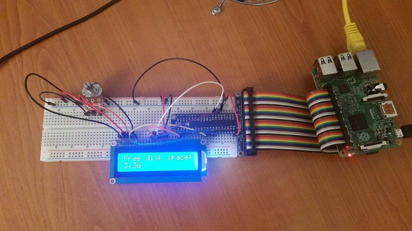
My 5V RaspberryPi fan was very loud and annoying, so I wanted a solution to regulate the fan depending on the Pi temperature.
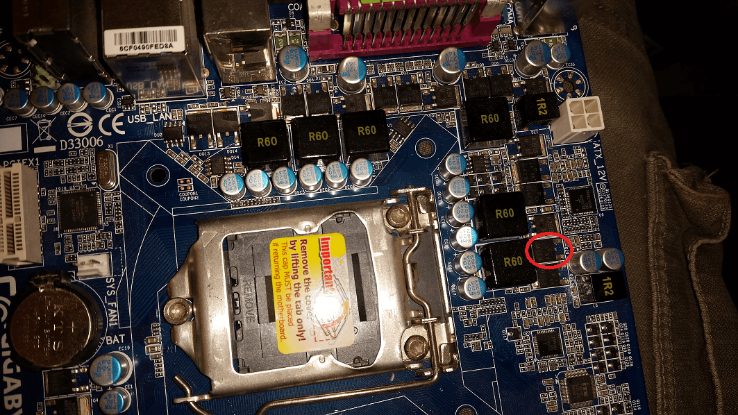
To achieve that, I used a mosfet switch, pulled out from an old computer motherboard, followed by some easy bash scripting.
Almost any mosfet from an old computer motherboard should work.
Wiring:
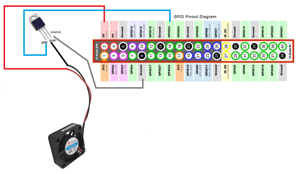
You can use any not used GPIO to connect the gate pin, in the picture above it’s #23.
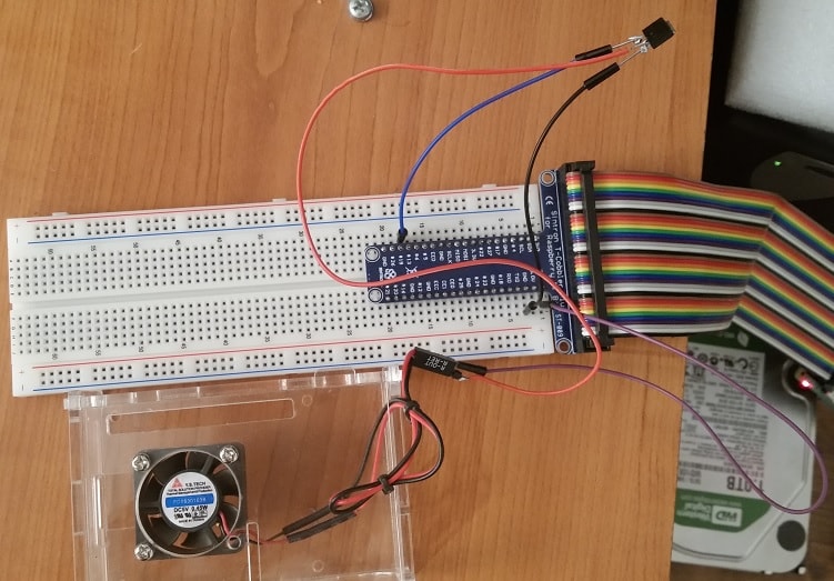
I connected the mosfet pin to GPIO 19 in my case. You can choose your own.
Software:
sudo apt-get update
sudo apt-get install bc
Enable selected GPIO pin, In my case, GPIO 19
echo "19" > /sys/class/gpio/export
echo "out" > /sys/class/gpio/gpio19/direction
If you wan’t to select another GPIO and you already exported one GPIO, you need to unexport previous GPIO.
echo "19" > /sys/class/gpio/unexport
Bash script for controlling fan “speed”:
pico rpipwm.sh
Paste the script bellow, edit your GPIO pin and save:
#!/bin/bash
#Poor man's PWM
#16.11.2015 by S55MA
#Quick and dirty script for controlling fan speed on RaspberryPI
#No rights reserved

#Define GPIO pin
pin="19"

while true; do

#Read temp
temp=$(cat /sys/class/thermal/thermal_zone0/temp | awk 'NR == 1 { print $1 / 1000}' | cut -c -4)

#If temperature is equal or lower than 39.99, the fan will stop spinning
if [[ $(bc <<< "$temp <= 39.99") == 1 ]] ;
then
$(echo "0" > /sys/class/gpio/gpio$pin/value)
fi

#If temperature is between 40 and 42.99, the fan will start with 1 second burst and 1 second sleep
if [[ $(bc <<< "$temp >= 40 && $temp <= 42.99") == 1 ]] ;
then
$(echo "1" > /sys/class/gpio/gpio$pin/value; sleep 1; echo "0" > /sys/class/gpio/gpio$pin/value; sleep 1)
fi

#If temperature is between 43 and 47.99, the fan will start with 1 second burst and 0.5 second sleep
if [[ $(bc <<< "$temp > 43 && $temp <= 47.99") == 1 ]] ;
then
$(echo "1" > /sys/class/gpio/gpio$pin/value; sleep 1; echo "0" > /sys/class/gpio/gpio$pin/value; sleep 0.5)
fi

#If temperature is equal or higher than 48, the fan will start spinning constantly
if [[ $(bc <<< "$temp >= 48") == 1 ]] ;
then
$(echo "1" > /sys/class/gpio/gpio$pin/value)
fi
sleep 0.1
done
chmod +x rpipwm.sh
./rpipwm.sh
Enable auto start at boot:
sudo cp rpipwm.sh /etc/init.d/rpipwm.sh
sudo chmod +x /etc/init.d/rpipwm.sh
sudo update-rc.d /etc/init.d/rpipwm.sh defaults
or you can use crontab:
crontab -e
Add and save:
@reboot /path/to/script/rpipwm.sh
sudo update-rc.d cron defaults