PfSense supports only outbound traffic shapping so you can’t shape multiple LAN/VLAN interfaces without putting another PfSense box in front of it. The only way to shape it is to use only one physical interface LAN and tag other VLANS on that interface. You need to select only WAN and LAN interface for traffic shaping. All traffic that will pass from VLANs will go trough LAN interface where QOS traffic shaper will catch it. If you don’t do it via only one interface, traffic shaping will work, but the VLAN to VLAN traffic will be limited to the speed of a WAN download bandwidth.
For start, you can use traffic shaping wizard and modify rules after.
Go to:
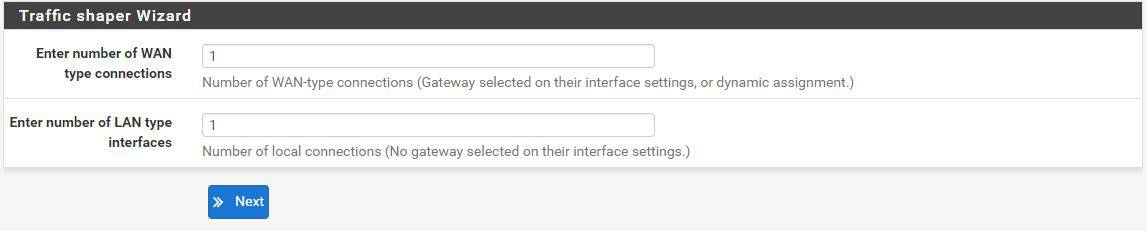
Firewall -> Traffic Shaper -> Wizards -> Multiple LAN/WAN
Select one WAN connection and one LAN connection:
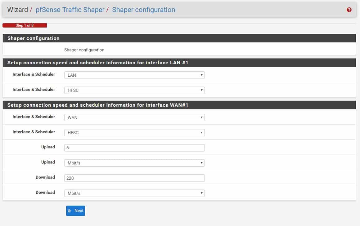
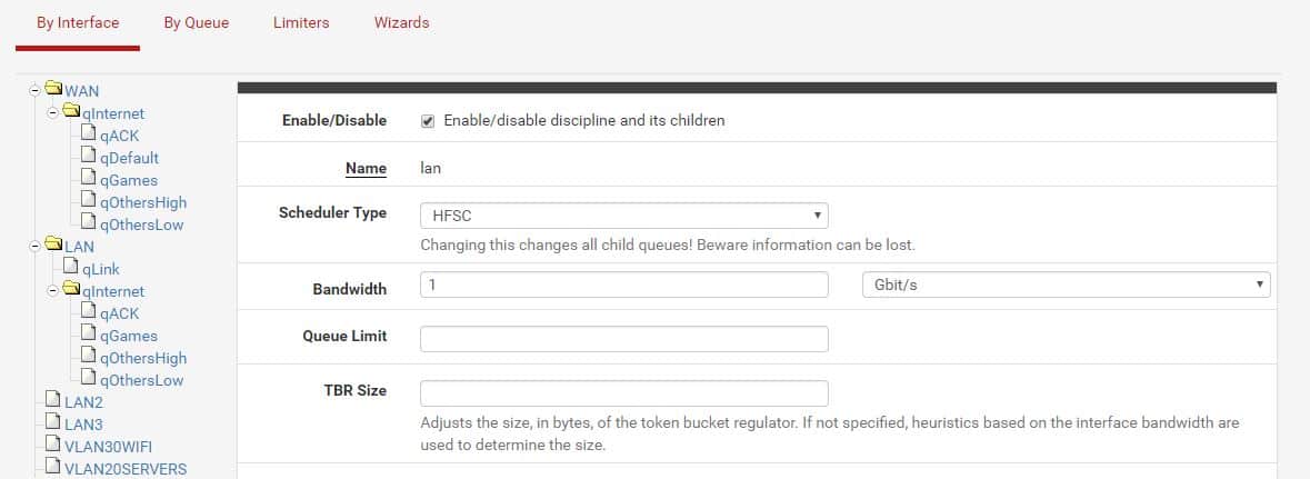
For interface select LAN and WAN, scheduler should be HFSC (you can choose another one if you like, but this post is about HFSC setup).
Define your WAN upload and download speed and continue wizzard till the end and save.
Go to:
Firewall -> Traffic shaper
Click on LAN and set bandwidth to your physical interface speed.
Set qLink bandwidth percentage to: ((LAN bandwidth – WAN download bandwidth) / 10)
Example:
My LAN bandwidth = 1000 Mbit
My WAN download banwidth = 200 Mbit
(1000 – 200) / 10 = 80%
The sum of parent trees has to be 100%
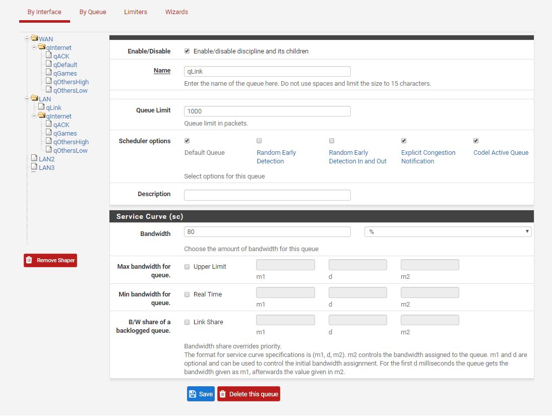
Save.
All you have to do now is add two more floating rules. Rules added by the wizzard are good enough to get an idea how it works. You can later add custom ports, depends on what you need.
Go to:
Firewall -> Rules -> Floating
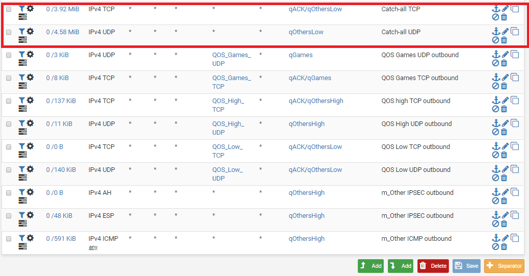
We will add a rule to catch all traffic that does not fall under defined floating rules created by the wizzard. We will put all not defined traffic to qOtherLow queue. The important thing is to have rules added at the top of the floating rules and not at the bottom.
Add rule 1:
Match, interface: WAN, direction: any, protocol: TCP, source: any, destination: any, destination port range: from any to any
Advanced options: Ackqueue / Queue: qACK / qOtherLow

Add rule 2:
Match, interface: WAN, direction: any, protocol: UDP, source: any, destination: any, destination port range: from any to any
Advanced options: Ackqueue / Queue: none / qOtherLow

The two created rules have to be at the top:
Basic traffic shaping should work now. It’s up to you know to fine tune the rules. Check the status of traffic shaper at Status -> Queues
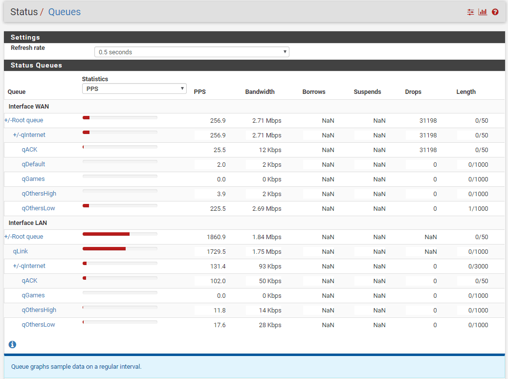
qLink queue is VLAN <-> VLAN traffic while all the queues bellow +/-qInternet are VLAN <-> WAN traffic
Downsides of this setup:
- You are limited to only one physical interface for VLAN traffic meaning your VLAN to VLAN bandwidth can suffer with multiple heavy users on a local network (like transferring a lot of files from local servers to local clients). You could probably solve that with LAN bridges but I don’t know how a QOS would behave in that case.
- You can’t run squid proxy service because download traffic on port 80 and 443 will bypass traffic shaper (it can probably be done with some tweaking but I haven’t tested it yet).