Scenario:

When you have only one interface connected and you add another interface to the same machine (in my case VLAN interface), there will be 2 default routes: one for each interface, in my test lab ens18 and ens19.50. Both will initially have a default route metric of 100. The metric is a measure of route priority, where a higher metric means lower priority.

ens18 will be used for server management and ens19.50 will be used for qBittorent Docker container. I want to mount a NAS share to the host, to which a qBittorent Docker container would have access to. Because both routes have the same metric, we don’t know from which interface a samba share would be mounted. I don’t want my samba share to be mounted via management interface, because all traffic from torrents to NAS will go through management interface, and we don’t want that. Firstly ens18 is only 1 Gbps while ens19.50 is 10 Gbps and secondly, traffic flow from ens19.50 to ens18 is forbidden on my firewall, so Docker container wouldn’t be able to save files.

Tested on Ubuntu server 24.04 LTS.

Goals:

  • ens18: Used for server management.
  • ens19.50: Used for a qBittorrent Docker container.
  • Mount a NAS share to the host, accessible by the qBittorrent Docker container directly.

Problem:

With both routes having the same metric, the system might mount the Samba share via the ens18 management interface. This is not desirable because:

  1. Bandwidth Limitation: ens18 is only 1 Gbps, while ens19.50 is 10 Gbps.
  2. Firewall Restrictions: Traffic flow from ens19.50 to ens18 is forbidden on my firewall, preventing the Docker container from saving files to the NAS if it were mounted via ens18. That means, torrent traffic would flow from ens19.50 to NAS via ens18, because samba share is mounted via ens18.

Solution:

To ensure that traffic to the NAS goes through the 10 Gbps ens19.50 interface, we will:

  1. Change the Metric: Adjust the metric for the default route on ens19.50 to 200, making it a lower priority for general traffic.
  2. Add a Specific Route: Add a specific route for the NAS (192.168.20.5) via ens19.50.

Network Configuration:

  • ens18: untagged interface (management)
    • IP: 172.16.210.105
    • Mask: 255.255.255.0
    • Gateway: 172.16.210.1
  • ens19.50: created on trunk interface (VLAN50 – torrent traffic) 
    • IP: 192.168.50.100
    • Mask: 255.255.255.0
    • Gateway: 192.168.50.1
    • Docker network type is macvlan
  • NAS server: (torrent flow destination)
    • IP: 192.168.20.5

Ens18 and ens19.50 both receive their IP configuration via DHCP server. I prefer creating static DHCP reservation on my firewall than entering IPs manually to each device.

Steps:

  1. Understand Route Metrics:
    • Each route has a metric.
    • Lower metric means higher priority.
    • We will change the metric of the default route for ens19.50 to 200, so ens18 will be preferred for all traffic except 192.168.20.5.
  2. Edit Netplan Configuration:
    • We will edit the netplan configuration to set the route metrics and add a specific route for 192.168.20.5.

Instructions:

  1. Open the Netplan Configuration File:
    • Open a terminal.
    • Use a text editor to edit the netplan configuration file /etc/netplan/vlans.yaml.
  2. Configure the Interfaces and Routes:
    • Add the following configuration:

network: version: 2 ethernets: ens19: dhcp4: no ens18: dhcp4: true vlans: ens19.50: id: 50 link: ens19 dhcp4: true dhcp4-overrides: route-metric: 200 routes: - to: 192.168.20.5/32 via: 192.168.50.1

Explanation:

  • ethernets: Defines the parent interface ens19 and the primary interface ens18.
  • vlans: Defines the VLAN interface ens19.50 with VLAN ID 50.
    • dhcp4-overrides: Sets the route metric for ens19.50 to 200.
    • routes: Adds a specific route for 192.168.20.5 via 192.168.50.1
  1. Apply the Configuration:
    • Apply the netplan configuration with the following command:

netplan apply

  1. Verify the Routing Table:
      • Check the routing table to ensure the configuration is correct:

    ip route

      • You should see:

    default via 172.16.210.1 dev ens18 proto dhcp src 172.16.210.105 metric 100 default via 192.168.50.1 dev ens19.50 proto dhcp src 192.168.50.100 metric 200 192.168.50.1 dev ens19.50 proto dhcp scope link src 192.168.50.100 metric 200

    Result:

    • Traffic to 192.168.20.5 will go via ens19.50 (VLAN50).
    • All Other Traffic: Will go via ens18 because its metric is 100, which has higher priority over ens19.50 with a metric of 200.

    When we mount the share, we can see in our pfsense firewall, the connection was successfully established from 192.168.50.100 (ens19.50) to 192.168.20.5 (NAS)

    Notes:

    • The dhcp4-overrides section in the netplan file allows you to specify DHCP options, including setting the route metric.
    • Specific routes added in the routes section ensure that traffic to 192.168.20.5 uses the desired interface.

    What is Policy-Based Routing?

    Policy-based routing (PBR) is a technique used to make routing decisions based on policies set by network administrators. These policies can be based on various criteria such as source or destination IP addresses, protocols, or traffic types. In this example, we are using PBR to route traffic to a specific IP address (192.168.20.5) through a specific interface (ens19.50).

    Starting with version 8.5, Cisco has introduced an innovative feature to its Wireless LAN Controller (WLC): the Identity Pre-Shared Key, or iPSK. This functionality allows multiple devices, especially those unable to support WPA Enterprise authentication (802.1x), to connect to the same SSID but with unique credentials and configurations. This can be particularly useful in diverse device environments, such as those involving various IoT devices.

    A common application of iPSK includes setting up distinct network access configurations for different devices on the same network. Here are two practical scenarios:

    Scenario 1: All devices connect to the same SSID using the same Wi-Fi password, yet they are assigned to different VLANs based on their identity.

    Scenario 2: Devices connect to the same SSID with distinct Wi-Fi passwords, and can either be on the same VLAN or separate VLANs depending on the configuration.

    While Scenario 1 is ideal for simplicity and home networks, may not offer the same level of security as Scenario 2. It is perfectly suited for home networks where the primary goal is to segment devices into different VLANs using the same password. This setup simplifies management without significantly compromising security, making it a practical choice for less complex environments.

    Scenario 2 is the optimal security configuration and offers the highest level of security. In this setup, each device is assigned its own unique password. This is particularly beneficial because if a device is compromised, the impact is isolated. You only need to revoke or change the password for the affected device without disrupting the connectivity of other devices on the network.

    Before diving into the specific scenarios of iPSK deployment, ensure you have the following foundational elements configured and operational:

    – WLC Controller and pfSense RADIUS Server Connection: Ensure that your Wireless LAN Controller (WLC) and pfSense RADIUS server are properly connected and communicating. This setup is crucial for authenticating devices on your network using iPSK.

    – VLAN Functionality: Configure VLANs on both the pfSense and WLC controller. On the pfSense, this involves setting up VLAN tagging and defining VLAN interfaces. On the WLC controller, VLANs should be configured under the ‘Interfaces’ section. Proper VLAN configuration is essential for segmenting network traffic and enhancing security.

    Having these elements in place will provide a solid foundation for implementing the iPSK scenarios described, ensuring a smoother and more secure deployment.

    My lab setup was done on Cisco WLC 2504 (8.5.105.0) and PfSense (2.7.2).

    Setting Up Scenario 1: Single Password with VLAN Assignment on the same SSID

    To configure iPSK with VLAN assignments using the same password for all devices, follow these steps on your pfSense and WLC controller:

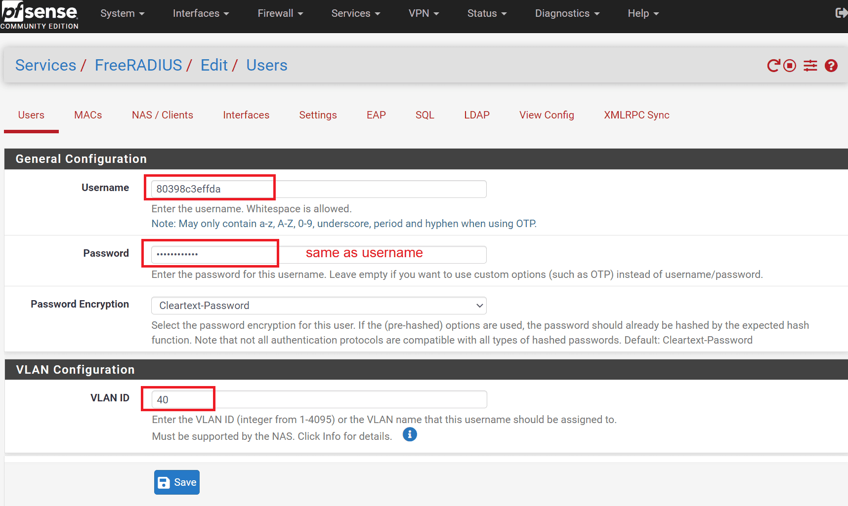
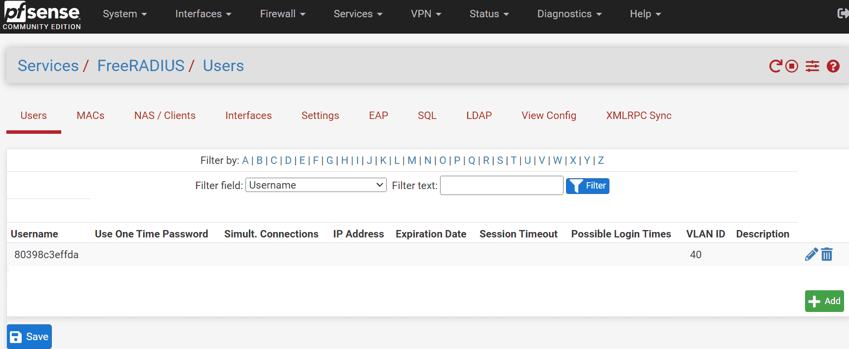
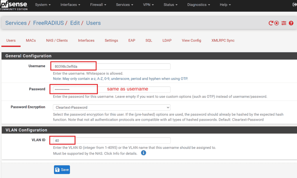
    1 Configure Users in pfSense:

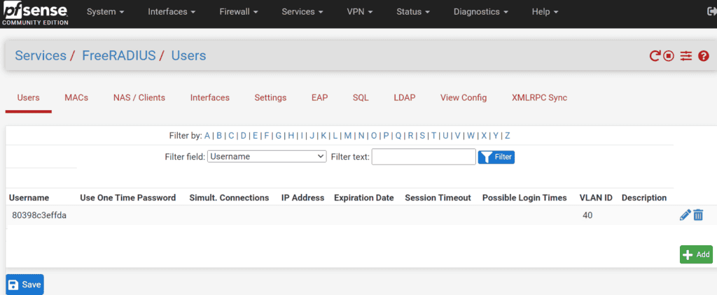
    • Navigate to Services -> FreeRADIUS -> Users on your pfSense interface.
    • Create a new user entry where both the username and password are the MAC address of the client device, formatted without separators. For instance, if the MAC address is 80:39:8c:3e:ff:da, you would use 80398c3effda for both the username and password. If you’re using Android clients, make sure you disable randomize MAC option in wifi settings and use Phone MAC instead.

    2 Assign VLANs:

    • When creating the user, also assign the desired VLAN to this username. This VLAN is where the device will be placed upon successful authentication.


    3. configure WLAN in WLC for scenario 1:

    To set up the WLAN that will be used with iPSK, follow these detailed steps within your Cisco Wireless LAN Controller (WLC):

    3.1 Create a New WLAN:

    • Navigate to the WLANs section in the WLC interface.
    • Click on Create New WLAN to start the setup process.

    3.2 General Settings:

    • In the General tab, provide a Profile Name and the SSID (Service Set Identifier) for your new WLAN.
    • Make sure to set the WLAN status to Enabled to activate it upon creation.

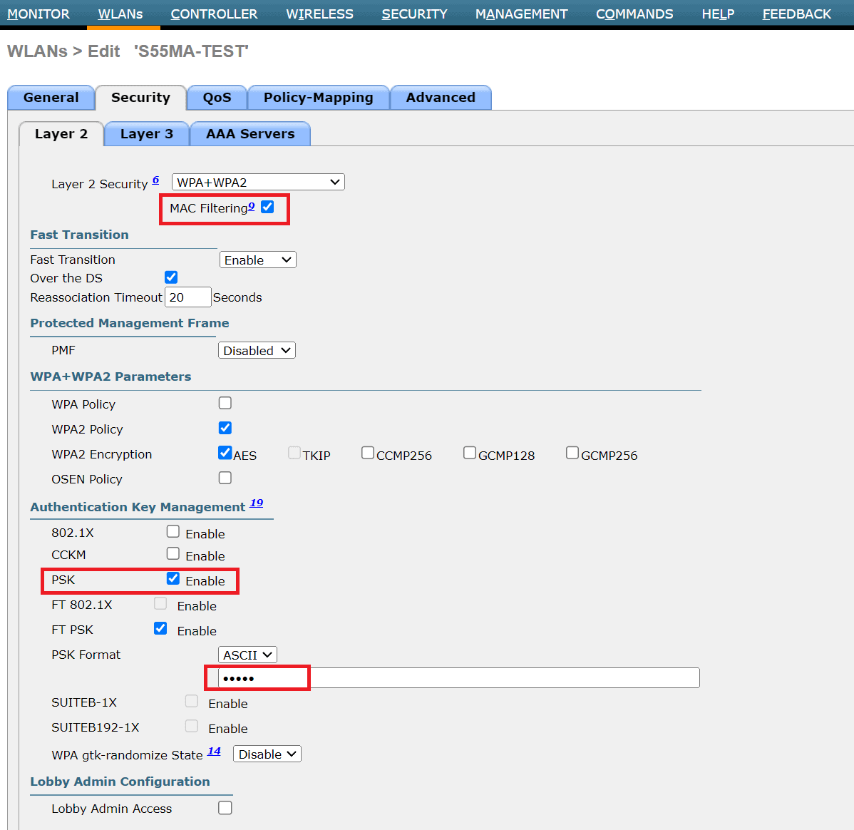
    3.3 Security Settings:

    • Go to the Security tab and then to the Layer 2 sub-tab.
    • Enable MAC Filtering to restrict access based on the MAC addresses of client devices.
    • Additionally, enable the PSK (Pre-Shared Key) option to set a universal Wi-Fi password for all devices. Directly beneath the PSK settings, enter the Wi-Fi password you desire in the PSK Format field.
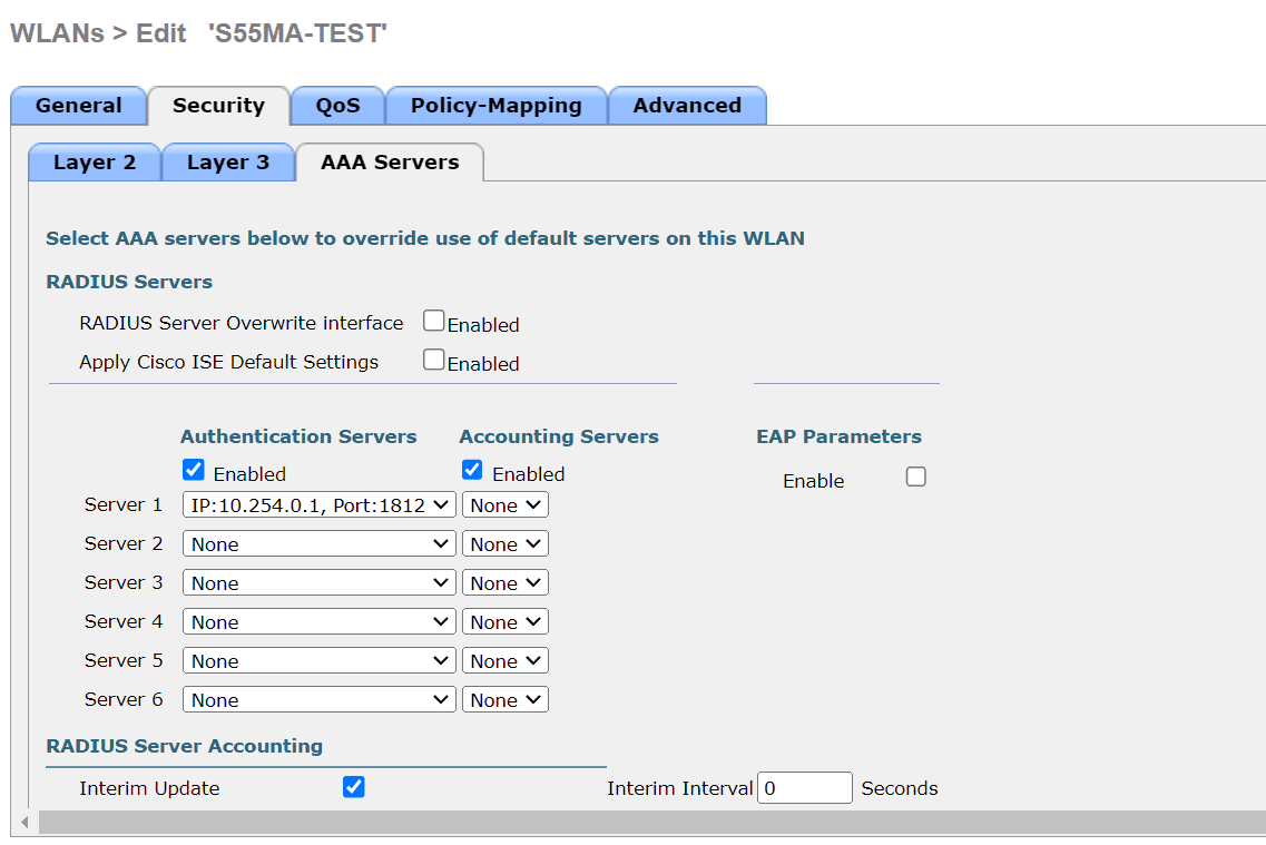
    3.4 Radius server

    • Go to the security tab and then to the AAA Server sub-tab
    • Under Server 1, select your radius server, which should be already set from required prerequisites
    • Apply settings and try to connect the client

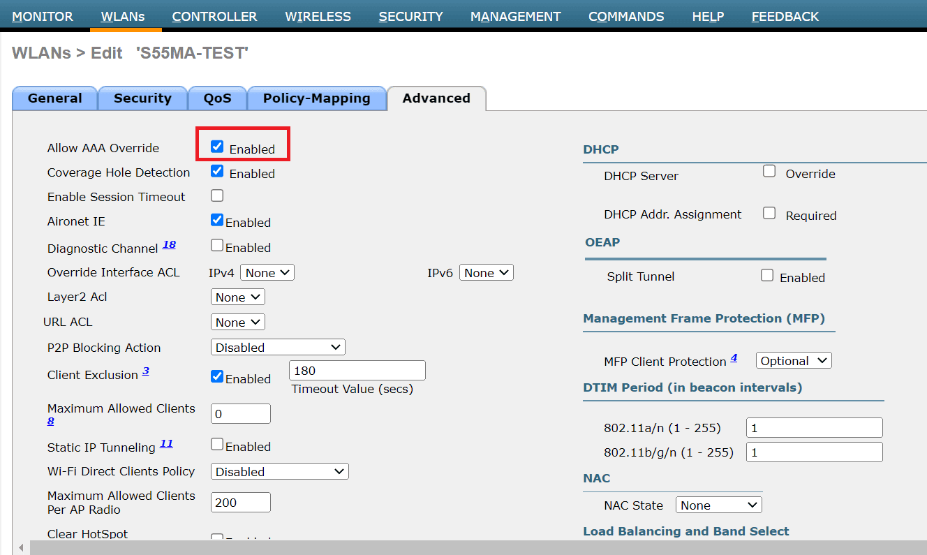
    3.5 Advanced settings

    • Go to Advanced tab and enable Allow AAA Override. This means, radius server will push settings like VLAN, QOS and other optional stuff.

    Authentication workflow in scenario 1 is:

    • When a client attempts to connect to the Wi-Fi network, the WLC will initially check the Wi-Fi universal password (PSK).
    • After the PSK validation, the WLC will forward the authentication request to the pfSense RADIUS server to verify if the client’s MAC address matches the username and password configured in RADIUS.
    • If a match is found, the user is authorized and placed into the correct VLAN. If no matching user entry exists for the MAC address, the Wi-Fi connection attempt will fail.
    • If the VLAN specified for a client in the pfSense RADIUS server does not exist on the Cisco WLC, or if it is not properly configured in the WLC settings, the client device will not be assigned to the intended VLAN. Instead, the device will default to the VLAN associated with the WLC’s default interface for that particular WLAN.

    Setting Up Scenario 2: Unique Passwords with VLAN Assignment on the same SSID

    This scenario allows each user to have a unique password, enhancing security by isolating potential breaches to individual devices. Follow these steps to configure unique passwords per user in pfSense using FreeRADIUS:

    2.1 Edit User Configuraton:

    • Navigate to Services -> FreeRADIUS -> Users in the pfSense interface.
    • Select and edit the user configuration set up in Scenario 1.

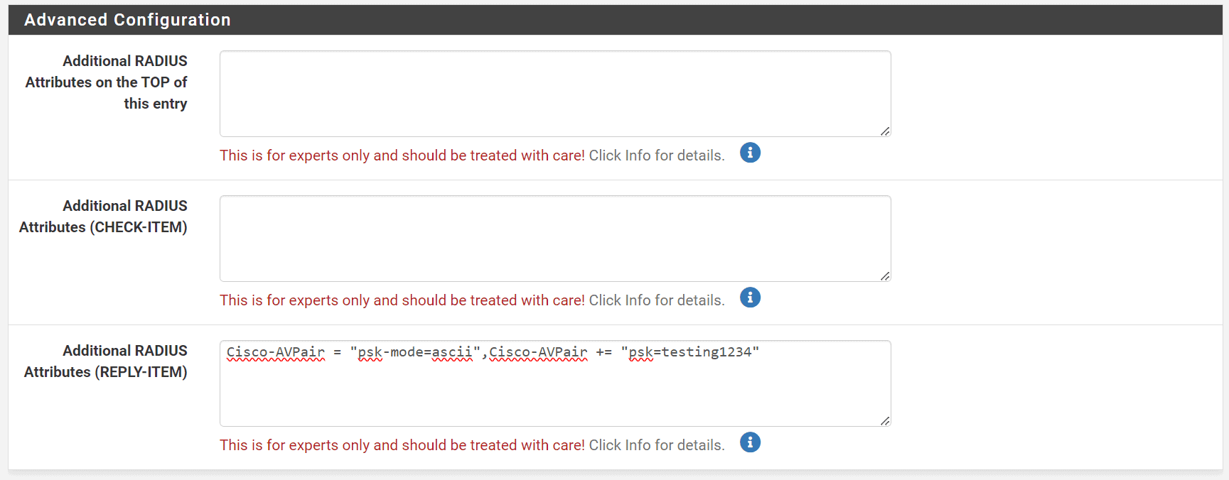
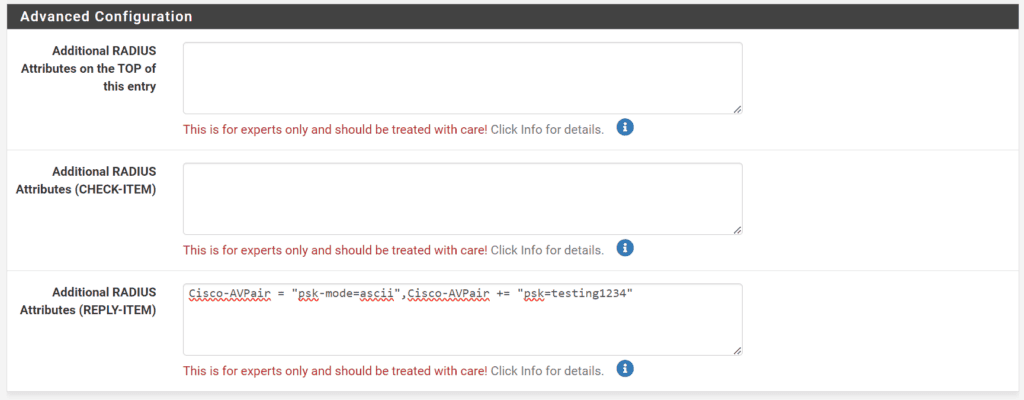
    2.2 Configure Additional RADIUS Attributes:

    • Scroll to the bottom of the user settings to find the field labeled Additional RADIUS Attributes (REPLY-ITEM).
    • Add Cisco AV Pairs to define unique passwords for each device
    • Enter Cisco-AVPair = “psk-mode=ascii” to specify that the password is in plain text.
    • Add Cisco-AVPair += “psk=client_unique_wifi_cleartext_password” where client_unique_wifi_cleartext_password is the unique password you assign to this user. Replace client_unique_wifi_cleartext_password with the actual password you intend to use.
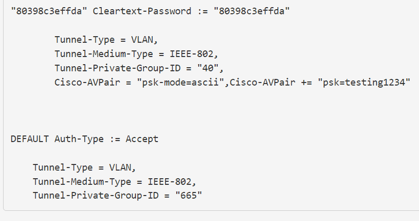
    • The whole entry should look like: Cisco-AVPair = “psk-mode=ascii”,Cisco-AVPair += “psk=client_unique_wifi_cleartext_password”

    2.3 Save the configuration

    2.4 Connect to the Network

    • Attempt to connect a device using the new unique password set in the RADIUS attributes.
    • Ensure that the device’s MAC address randomization feature is turned off to avoid connection issues due to unrecognized MAC addresses.

    Authentication workflow in scenario 2 is:

    • When a client attempts to connect to the Wi-Fi network with Radius password, the WLC will forward the authentication request to Radius to validate user.
    • If a match is found, the user is authorized and placed into the correct VLAN. If no matching user entry exists for the MAC address, the Wi-Fi connection attempt will fail.
    • If the VLAN specified for a client in the pfSense RADIUS server does not exist on the Cisco WLC, or if it is not properly configured in the WLC settings, the client device will not be assigned to the intended VLAN. Instead, the device will default to the VLAN associated with the WLC’s default interface for that particular WLAN.

    Steps to configure fallback VLAN in FreeRADIUS on PfSense:

    In both Scenario 1 and Scenario 2, you need to have a valid RADIUS user. If you try to use the universal WiFi password defined in the WLC, it won’t work. To use a fallback VLAN with a universal password for users not defined in RADIUS, you need to add additional parameters in the FreeRADIUS configuration. SSH into your pfSense system and open the file at /usr/local/etc/raddb/users.

    Add this to the end of the file:

    DEFAULT Auth-Type := Accept
    
        Tunnel-Type = VLAN,
        Tunnel-Medium-Type = IEEE-802,
        Tunnel-Private-Group-ID = "665"

    Change “665” to your desired fallback VLAN. Save the file and restart the Radius server. Ensure that this entry is always at the end of the file when adding new users.

    In your PfSense GUI, it should look something like this:

    Now, you can connect a device without a RADIUS user to the WiFi using the universal password. It will default to VLAN 665.

    Caveat: editing config files directly from shell is tricky for PfSense, because everytime you change a config via GUI, config edite from shell will get rewritten, and all your changes will be gone. The same will happen with reboot. If you wan’t to make a change permanent, you should make a cronjob that adds manual config at reboot, or edit main template file radius.inc found at /usr/local/pkg/freeradius.inc.

    Example:

    • Connecting with a user defined in RADIUS will result in a successful connection to WiFi with the VLAN assigned to that user.
    • Connecting to WiFi with the universal password will result in a successful connection with the VLAN defined under DEFAULT Auth-Type := Accept, in this case, VLAN 665.

    You can use both WLC universal password and radius user password to connect to WiFi, depending on your needs. Ensure your fallback VLAN is securely configured.

    References:
    https://www.linkedin.com/pulse/shared-ssid-ciscos-identity-psk-freeradius-alexandru-panaitescu/
    https://www.wifireference.com/2017/12/10/cisco-identity-psk-what-is-it-and-how-is-it-configured/
    https://www.cisco.com/c/en/us/support/docs/security-vpn/remote-authentication-dial-user-service-radius/116291-configure-freeradius-00.html
    https://goodwi.fi/posts/2023/09/ipsk-no-ise-freeradius/


    You need to manually reapply some settings in Cisco DNAC after the upgrade.

    Currently I noticed two issues after upgrading DNAC in all previous version including the latest (currently on 2.3.5.5):

    – Backups stop working. Solution is to reapply settings. It’s enough to modify one letter in Server Path in NFS tab and click Apply:

    – DNAC can’t reach ISE PAN server (ISE PAN ERS reachability failed for ISE server). Solution is to reapply ISE server connections, just enter the password again and apply it. Settings are located in System Settings, Authentication and Policy servers:

    I recently experienced an issue with my Hikvision doorvilla DS-KV8113-WME1(B), which was connected to my network via WiFi. On occasion, especially following a power outage, the device would lose its WiFi settings. This required me to disassemble the unit, connect it via a UTP cable, and reconfigure the settings—a frustrating and time-consuming process. Due to this, I wouldn’t recommend this particular Hikvision model.

    To resolve this, I decided to implement a workaround by using the smallest WiFi access point (AP) I could find, placing it in the wall cavity behind the Hikvision unit, and connecting the device to this AP via a UTP cable. Essentially, I created a WiFi-to-Ethernet bridge. The AP I chose for this task was the Mikrotik RBcAPL-2nD.

    However, connecting a Mikrotik device to a non-Mikrotik device in a pseudobridge setup has certain limitations, as detailed in their official documentation: Mikrotik Wireless Station Modes.

    Despite these limitations, I managed to get it functioning with my PfSense system, but with a few caveats:

  • The client device (in this case, the Hikvision unit) must be assigned a static IP, as DHCP does not function over a pseudobridge.
  • The client’s IP address must belong to the same subnet that the WiFi AP is connected to.
  • It’s necessary to disable the spanning-tree protocol in the Mikrotik settings. Be sure to apply all your configurations beforehand, as you will lose access to the Mikrotik management interface after this change.
  • Here’s a brief guide on what you need to do:

  • Set up a WiFi profile on your Mikrotik device to connect to your existing WiFi network.
  • Change the station mode to pseudobridge.
  • Disable the DHCP server.
  • Turn off the spanning-tree protocol.
  • Below is the complete configuration. Replace “YOUR-WIFI-SSID” and “YOUR-WIFI-PASS” with your network’s details.

    # oct/19/2023 17:21:59 by RouterOS 6.48.7
    # software id = M2DK-HSWA
    #
    # model = RBcAPL-2nD
    # serial number = HET091AHV58
    /interface bridge
    add comment=defconf name=bridge
    /interface list
    add comment=defconf name=WAN
    add comment=defconf name=LAN
    /interface wireless security-profiles
    set [ find default=yes ] supplicant-identity=MikroTik
    add authentication-types=wpa-psk,wpa2-psk mode=dynamic-keys name=YOUR-WIFI-SSID \
        supplicant-identity=MikroTik wpa-pre-shared-key=YOUR-WIFI-PASS \
        wpa2-pre-shared-key=YOUR-WIFI-PASS
    /interface wireless
    set [ find default-name=wlan1 ] band=2ghz-g/n channel-width=20/40mhz-XX \
        country=slovenia disabled=no distance=indoors frequency=auto \
        installation=indoor mode=station-pseudobridge security-profile=YOUR-WIFI-SSID \
        ssid=YOUR-WIFI-SSID wireless-protocol=802.11
    /ip hotspot profile
    set [ find default=yes ] html-directory=hotspot
    /ip pool
    add name=default-dhcp ranges=192.168.88.10-192.168.88.254
    /ip dhcp-server
    add address-pool=default-dhcp interface=bridge name=defconf
    /interface bridge port
    add bridge=bridge comment=defconf interface=wlan1 multicast-router=disabled \
        trusted=yes
    add bridge=bridge interface=ether1 multicast-router=disabled trusted=yes
    add bridge=bridge disabled=yes interface=all
    /ip neighbor discovery-settings
    set discover-interface-list=LAN
    /interface list member
    add comment=defconf interface=bridge list=LAN
    add comment=defconf interface=ether1 list=WAN
    /ip address
    add address=192.168.88.1/24 comment=defconf disabled=yes interface=bridge \
        network=192.168.88.0
    /ip dhcp-client
    # DHCP client can not run on slave interface!
    add comment=defconf disabled=no interface=ether1
    add disabled=no interface=bridge
    /ip dhcp-server network
    add address=192.168.88.0/24 comment=defconf gateway=192.168.88.1
    /ip dns
    set allow-remote-requests=yes
    /ip dns static
    add address=192.168.88.1 comment=defconf name=router.lan
    /ip firewall filter
    add action=accept chain=input comment=\
        "defconf: accept established,related,untracked" connection-state=\
        established,related,untracked
    add action=drop chain=input comment="defconf: drop invalid" connection-state=\
        invalid
    add action=accept chain=input comment="defconf: accept ICMP" protocol=icmp
    add action=accept chain=input comment=\
        "defconf: accept to local loopback (for CAPsMAN)" dst-address=127.0.0.1
    add action=drop chain=input comment="defconf: drop all not coming from LAN" \
        in-interface-list=!LAN
    add action=accept chain=forward comment="defconf: accept in ipsec policy" \
        ipsec-policy=in,ipsec
    add action=accept chain=forward comment="defconf: accept out ipsec policy" \
        ipsec-policy=out,ipsec
    add action=fasttrack-connection chain=forward comment="defconf: fasttrack" \
        connection-state=established,related
    add action=accept chain=forward comment=\
        "defconf: accept established,related, untracked" connection-state=\
        established,related,untracked
    add action=drop chain=forward comment="defconf: drop invalid" \
        connection-state=invalid
    add action=drop chain=forward comment=\
        "defconf: drop all from WAN not DSTNATed" connection-nat-state=!dstnat \
        connection-state=new in-interface-list=WAN
    /ip firewall nat
    add action=masquerade chain=srcnat comment="defconf: masquerade" \
        ipsec-policy=out,none out-interface-list=WAN
    /ip service
    set telnet disabled=yes
    set ftp disabled=yes
    set www-ssl disabled=no
    set api disabled=yes
    set api-ssl disabled=yes
    /system clock
    set time-zone-name=Europe/Ljubljana
    /system identity
    set name=RouterOS
    /tool mac-server
    set allowed-interface-list=LAN
    /tool mac-server mac-winbox
    set allowed-interface-list=LAN
    

    If you have your mailinabox installation behind HTTP reverse proxy, such as nginx proxy manager for example, mailinabox will send you emails each day with subject TLS Certificate Provisioning Result, containing errors.

    That’s because it fails to install let’s encrypt certificates. Your web certificates are handled by your reverse proxy, so you don’t need mailinabox to do that. To disable certificate provisioning, open file:
    /root/mailinabox/management/daily_tasks.sh and comment out this line:

    management/ssl_certificates.py -q 2>&1 | management/email_administrator.py “TLS Certificate Provisioning Result”

    Restart service:

    systemctl restart mailinabox

    Did you install the Mailinabox (Mail-in-a-Box) solution and discover that your admin interface is publicly accessible? Me too, and there are no settings to limit this via GUI. My goal was to access admin interface only via my local network IP.

    The Mail-in-a-Box web server runs on Nginx, and limiting IP access in Nginx is pretty simple. First, you need to find the config file. The default location in Mail-in-a-Box is /etc/nginx/conf.d/local.conf. But this file is overwritten if any changes are detected. So you actually need to modify two files, /etc/nginx/conf.d/local.conf and the template config file /root/mailinabox/conf/nginx-primaryonly.conf which Mail-in-a-Box uses to populate local.conf file. Open both files and modify the following section:

    location /admin/assets {
                    alias /usr/local/lib/mailinabox/vendor/assets;
            }
            rewrite ^/admin$ /admin/;
            rewrite ^/admin/munin$ /admin/munin/ redirect;
            location /admin/ {
                    proxy_pass http://127.0.0.1:10222/;
                    proxy_set_header X-Forwarded-For $remote_addr;
                    add_header X-Frame-Options "DENY";
                    add_header X-Content-Type-Options nosniff;
                    add_header Content-Security-Policy "frame-ancestors 'none';";
            }
    

    Change it to:

    location /admin/assets {
                    alias /usr/local/lib/mailinabox/vendor/assets;
            }
            rewrite ^/admin$ /admin/;
            rewrite ^/admin/munin$ /admin/munin/ redirect;
            location /admin/ {
                    proxy_pass http://127.0.0.1:10222/;
                    proxy_set_header X-Forwarded-For $remote_addr;
                    add_header X-Frame-Options "DENY";
                    add_header X-Content-Type-Options nosniff;
                    add_header Content-Security-Policy "frame-ancestors 'none';";
                    allow 192.168.60.2;
                    deny all;
            }
    

    We added the line “allow 192.168.60.2;” to grant admin access to the IP 192.168.60.2 and the line “deny all;” to deny access to everyone else. If you’re not running a reverse proxy in front of Mail-in-a-Box, you’re done. Be sure to change 192.168.60.2 to your local IP.

    Save the changes and reload Nginx with the following command:

    sudo service nginx reload

    If you’re running a reverse proxy in front of Mail-in-a-Box, such as nginx proxy manager, you need to add some more settings to the Mail-in-a-Box nginx.conf file. When the reverse proxy passes requests to Mail-in-a-Box, it uses its own IP (the IP of the reverse proxy), so each request appears to come from the reverse proxy IP instead of the client’s IP. This would result in blocking all clients.

    To circumvent this and obtain the correct client’s IP, you need to enable the Real IP Header module in the Mail-in-a-Box nginx.conf file. First open another template file /root/mailinabox/conf/nginx.conf, find this section and modify it:

    # The secure HTTPS server.
    server {
            listen 443 ssl http2;
            listen [::]:443 ssl http2;
            server_name $HOSTNAME;
    ...
    

    Change it to:

    # The secure HTTPS server.
    server {
            listen 443 ssl http2;
            listen [::]:443 ssl http2;
    
            real_ip_header X-Forwarded-For;
            real_ip_recursive on;
            set_real_ip_from 0.0.0.0/0;
    
            server_name $HOSTNAME;
    ...
    

    Now open /etc/nginx/conf.d/local.conf and find this section:

    # The secure HTTPS server.
    server {
            listen 443 ssl http2;
            listen [::]:443 ssl http2;
            server_name yourdomain.com;
    ...
    

    Change it to:

    # The secure HTTPS server.
    server {
            listen 443 ssl http2;
            listen [::]:443 ssl http2;
    
            real_ip_header X-Forwarded-For;
            real_ip_recursive on;
            set_real_ip_from 0.0.0.0/0;
    
            server_name yourdomain.com;
    ...
    

    Be sure to change yourdomain.com to your own domain.

    Save the changes and reload Nginx with the following command:

    sudo service nginx reload

    Try accessing the admin interface from your local IP and then from another IP. Your local IP should have access, but other IPs should receive a forbidden error.

    Here’s an example of the access log:

    tail -f /var/log/nginx/access.log
    192.168.60.2 - - [16/Jun/2023:17:59:15 +0200] "GET /admin HTTP/1.1" 200 39073
    188.196.15.222 - - [16/Jun/2023:17:59:18 +0200] "GET /admin HTTP/1.1" 403 180
    

    We can see that my local IP received a response code of 200, indicating a successful request, while the second IP received a response code of 403, meaning the server understood the request but refused to authorize it.

    We modified the following files:

    Running config files:
    /etc/nginx/conf.d/local.conf

    Template files:
    /root/mailinabox/conf/nginx-primaryonly.conf
    /root/mailinabox/conf/nginx.conf

    In Cisco DNA center, version 2.3.3.6, under System -> Settings -> Trust & Privacy -> Device Certificate and PKI Certificates, you get an error message saying:

    Internal Server Error: An unexpected condition was encountered. Please try after the system is restored.
    

    Current solution is to restart pki broker and jboss service from DNAC shell.

    magctl service restart -d apic-em-pki-broker-service
    magctl service restart -d apic-em-jboss-ejbca
    

    Wait a few minutes after restart and try again.

    This is probably related to this bug: https://bst.cisco.com/bugsearch/bug/CSCwd25799

    Install npm, Puppeteer and dependencies:

    apt update -y && apt upgrade -y
    apt install -y npm
    apt install -y libx11-xcb1 libxcomposite1 libxcursor1 libxdamage1 libxi-dev libxtst-dev libnss3 libcups2 libxss1 libxrandr2 libasound2 libatk1.0-0 libatk-bridge2.0-0 libpangocairo-1.0-0 libgtk-3-0 libgbm1
    npm install -g n
    n lts
    hash -r
    npm install puppeteer
    

    Install Chrome without snap:

    wget https://dl.google.com/linux/direct/google-chrome-stable_current_amd64.deb
    apt install ./google-chrome-stable_current_amd64.deb
    

    Make a test file test.js:

    const puppeteer = require('puppeteer');
    const fs = require('fs');
    
    async function run () {
      const browser = await puppeteer.launch({
        executablePath: '/usr/bin/google-chrome-stable',
        args: ['--no-sandbox'],
        defaultViewport: {width: 1920, height: 1080}
      });
      const page = await browser.newPage();
      await page.goto('https://www.google.com');
      await sleep(3000);
    
      await page.screenshot({path: 'screenshot.png'});
      const html = await page.content();
      fs.writeFileSync('source.htm', html);
    
      browser.close();
    }
    run();
    
    function sleep(ms) {
      return new Promise((resolve) => {
        setTimeout(resolve, ms);
      });
    } 
    

    Test it:

    node test.js
    

    When you are greeted by this error: Error code: SSL_ERROR_INTERNAL_ERROR_ALERT trying to access Cisco WLC via Web GUI, you need remove trustpoint TP-self-signed-X cert, and reenable http server. This will regenerate self signed cert.

    C9K5#show run | inc trustpoint TP-self
    crypto pki trustpoint TP-self-signed-2997515006
    
    C9K5#conf t
    Enter configuration commands, one per line.  End with CNTL/Z.
    
    C9K5(config)#no crypto pki trustpoint TP-self-signed-2997515006
    % Removing an enrolled trustpoint will destroy all certificates
     received from the related Certificate Authority.
    
    Are you sure you want to do this? [yes/no]: yes
    % Be sure to ask the CA administrator to revoke your certificates.
    
    C9K5(config)#no ip http server
    C9K5(config)#no ip http secure-server
    C9K5(config)#ip http server
    C9K5(config)#ip http secure-server
    C9K5(config)#ip http authentication local  
    

    Quick notes, how to add villa door station to hik-connect app, since Hikvision documentation is all over the place. We are assuming you already have network connectivity to the device.

    Goal: add villa door station to hik-connect app, so you can remote view your cameras on mobile app

    1. The device I’m configuring is DS-KV8113-WME1(B)

    2. You will need serial number. It’s located on the back of device, there is a sticker. Alternatively, login to your device via web interface. Go To configuration, System Settings, and there is a section Serial No. Select text and scroll with your mouse to the right. The actual serial number is last 9 characters:

    3. Create account and login at https://www.hik-connect.com/

    4. Enable platform access on your device. Go back to your device via web browser and go to Configuration, Network, Advanced, Platform Access. Click Enable, and setup Stream Encryption/Encryption Key. This is the part where Hikvision documentation is lacking. When you are going to add device to hik-connect app, you will be asked for serial number and verification code. Some devices have verification code written on the label, but my device doesn’t. The verification code is Stream Encryption/Encryption Key.

    5. Go back to https://www.hik-connect.com/ and click Add. You will be asked to enter serial number and verification code. If everything is done right, your devices will be online.

    6. Download hik-connect mobile app. I’m using Android. Here lies another CAVEAT. Don’t download app from Google Playstore, because they are not updating the app anymore. Hikvision has it’s own app store at: https://appstore.hikvision.com/. Download Hik-Connect – for End user, install it, login to your hik-connect account and you’re done. You should be able to view and operate your cams via their cloud remotely.

    A note of caution. Don’t put your camera in your bedroom, this goes on Hikvision cloud and they can probably spy on you, it’s a Chinese product nevertheless. Extra points if you put your device on separate VLAN and isolate it from the rest of your network.

    UPDATE: In the latest DNAC update, they changed things. In order to get root access now, Cisco support has to provide you a token. What a shame.

    Content bellow this point is no longer relevant to the new DNAC versions.

    In the newest version of Cisco DNA center, I think >= 2.3.3.6, root access is no more available by default. By default, you drop into so called magshell that’s running on BusyBox. This is not sufficient for serious debugging purposes. To enable root (bash shell) on DNA center, follow this steps.

    1: Connect to your DNA center via SSH, on port 2222 and enter the following CLI command to determine your shell type:

    magctl ssh shell display

    Active shell for current user: magshell

    2: Enable bash shell:

    _shell -c 'sudo magctl ssh shell bash'

    Password:
    Warning! Activity within this shell can jeopardize the functioning of the system!

    [sudo] password for maglev:

    Successfully enabled bash for user, will be effective from next login.

    3. To re-enable restricted shell, enter the following CLI command and password:

    sudo magctl ssh shell magshell

    [sudo] password for maglev:

    Successfully enabled magshell for user, will be effective from next login.

    Cisco DNA center currently lacks a feature to export all inventory. You can’t export serial numbers for power supplies and network modules. This bash script is very simple and primitive, it connects to Cisco device via SSH and collects inventory data. If you have a lot of devices, this will take a lot of time. You need to modify this script for parallel ssh connections if you have more than 100 devices. For more info, read the script comments.

    #!/bin/bash
    
    # SSH credentials for Cisco devices
    # For security reasons, make sure the user is read only capable
    user=CiscoUsername
    password=CiscoPassword
    
    # Path to file where IPs of devices are stored (one IP per line)
    file=devices.txt
    
    # Mail settings
    mailrelay="smtp=some.mail.server:25"
    sender=no-reply@somedomain.com
    mailto=some.user@somedomain.com
    mailsubject="inventory bash exporter - C9K2,C9K3,C9K5 devices"
    
    # Path to output file (exported inventory file)
    results=results.txt
    
    # Cleanup from before
    
    rm -f "$results"
    
    # Check if necessary files exist
    if [ ! -f "$file" ]; then
        echo
        echo "ERROR: Missing file with IP addresses. Exiting ..."
        echo
        exit 1
    fi
    
    lines=$(cat $file)
    
    for line in $lines
    do
            # Connect to device, read hostname and append output to file. I filter hostname by "-SDA-", because each device
            # contains "-SDA-" in hostname, in my case. You need to modify this to your own needs.
            sshpass -p "$password" ssh -t -q -o ConnectTimeout=5 -o StrictHostKeyChecking=no -o UserKnownHostsFile=/dev/null\
            "$user"@"$line" 'show run | i hostname' | grep "\-SDA\-" | sed 's/=//g' | sed 's/\//g' | sed 's/ //g' >> "$results"
    
            # Connect to device, read inventory, filter output to get desired results (you can modify this to your own needs)
            # and append output to file. I filter out SFP modules, FAN trays, Stack modules.
            sshpass -p "$password" ssh -t -q -o ConnectTimeout=5 -o StrictHostKeyChecking=no -o UserKnownHostsFile=/dev/null\
            "$user"@"$line" 'show inventory' | grep PID | awk '{print $2,$7,$8}' | sed 's/ //g' | grep -v "," | sort | uniq | sed 's/SN:/,Serial:/g' |\
            grep -v "SFP\|FANTRAY\|FTRJ\|GLC\|FTLF\|STACK" >> "$results"
    
            printf "\n" >> "$results"
    done
        # Send results to an email 
        echo "Export generated: $(date). See attachment." | mailx -r "$sender" -S "$mailrelay" -s "$mailsubject" -a "$results" -v "$mailto"
        echo
        # Send done message to console
        echo "Done, check "$results"! or email"
        echo
    

    Firefly III has a recurring transactions option. In order for that to work, you need to setup a cronjob. Without that, you get an error at the top of the page saying:

    It seems the cron job that is necessary to support recurring transactions has never 
    run. This is of course normal when you have just installed Firefly III, 
    but this should be something to set up as soon as possible. Please check 
    out the help-pages using the (?)-icon in the top right corner of the page.

    Firefly III has an API to which you make a get request that triggers recurring transactions update. API call URL is:

    http://FIREFLY_URL/api/v1/cron/TOKEN

    To generate a token, go to your Firefly GUI -> Options -> Profile -> Command line token and copy token to URL.

    Example:

    http://firefly.example/api/v1/cron/6c57c098904f6f4765b52a4bc493687p

    If you go to this URL now, your Firefly will run recurring transactions. Because we don’t want to do that manually, we will do it via cronjob that will run every day at 3 AM.

    You can do it on any Linux box with normal cronjob:

    crontab -e

    and add this line:

    0 3 * * * wget -qO- http://firefly.example/api/v1/cron/6c57c098904f6f4765b52a4bc493687p &> /dev/null

    Because we are running Firefly 3 in Docker, more neat option is to add Alpine linux image to our docker compose and run it along within stack:

    version: '3.3'
    
    services:
      app:
        image: fireflyiii/core:latest
        restart: always
        volumes:
          - firefly_iii_upload:/var/www/html/storage/upload
        env_file: stack.env
        ports:
          - 8080:8080
        depends_on:
          - db
      db:
        image: mariadb:10.8.2
        hostname: fireflyiiidb
        restart: always
        environment:
          - MYSQL_RANDOM_ROOT_PASSWORD=yes
          - MYSQL_USER=firefly
          - MYSQL_PASSWORD=secret_firefly_password
          - MYSQL_DATABASE=firefly
        volumes:
          - firefly_iii_db:/var/lib/mysql
      cron:
         image: alpine
         command: sh -c "echo \"0 3 * * * wget -qO- http://firefly.example/api/v1/cron/6c57c098904f6f4765b52a4bc493687p &> /dev/null\" | crontab - && crond -f -L /dev/stdout"
    volumes:
       firefly_iii_upload:
       firefly_iii_db:

    After the stack is running, enter a shell of your Alpine container and check if cronjob is present:

    crontab -l

    Had some issues with Cisco DNAC and Stealthwatch. After settings up Stealthwatch server and Netflow collector, some of SDA devices were not compatible with Stealthwatch. The reason was: “NBAR is enabled on this device“. In DNA center, NBAR and CBAR was actually disabled, but the problem stil persisted. CBAR and NBAR were previously enabled, but after disabling it, it did not clean all devices. Guess this is a “cleanup” bug in DNA center. Solution was to manually remove ip flow from affected devices.

    DNA center version: 2.3.3.4

    Screenshot of affected devices:

    Solution: Clear ip flow from all interfaces on affected device, and resync device in DNA center.

    Example:

    conf t
    int range gi1/0/1-48,Te1/1/1-4,Gi1/1/1-4
    no ip flow monitor dnacmonitor input
    no ip flow monitor dnacmonitor output
    end
    wr
    

    Go to DNA center, Inventory -> Select device -> Actions -> Inventory -> Resync device

    Wait couple of minutes, and you should be able to enable Stealthwatch for this device.

    There is a Python tool called pyang that can read yang files. To install it on Linux machine:

    apt install git python3-pip
    pip install pyang

    Now, git clone yang data model to your linux machine:

    cd ~;git clone https://github.com/YangModels/yang.git

    Pyang by itself is capable of reading yang and present it as a tree. To get xpath, we need to install additional plugin from here: https://github.com/NSO-developer/pyang-xpath
    Find your pyang installation, and put the the xpath plugin to the plugin folder:

    find /usr/local/lib -iname pyang
    /usr/local/lib/python3.10/dist-packages/pyang

    Download plugin:

    wget -O /usr/local/lib/python3.10/dist-packages/pyang/plugins/xpath.py https://raw.githubusercontent.com/NSO-developer/pyang-xpath/master/xpath.py

    Go to Yang model you cloned a few steps back (in this example, we’ll find xpath for Cisco IOS-XE cpu usage:

    cd ~/yang/vendor/cisco/xe/1781/

    Use xpath module on yang file to get xpath:

    pyang -f xpath Cisco-IOS-XE-process-cpu-oper.yang 
    >>> module: Cisco-IOS-XE-process-cpu-oper
    /cpu-usage
    /cpu-usage/cpu-utilization
    /cpu-usage/cpu-utilization/five-seconds
    /cpu-usage/cpu-utilization/five-seconds-intr
    /cpu-usage/cpu-utilization/one-minute
    /cpu-usage/cpu-utilization/five-minutes
    /cpu-usage/cpu-utilization/cpu-usage-processes
    /cpu-usage/cpu-utilization/cpu-usage-processes/cpu-usage-process
    /cpu-usage/cpu-utilization/cpu-usage-processes/cpu-usage-process/pid
    /cpu-usage/cpu-utilization/cpu-usage-processes/cpu-usage-process/name
    /cpu-usage/cpu-utilization/cpu-usage-processes/cpu-usage-process/tty
    /cpu-usage/cpu-utilization/cpu-usage-processes/cpu-usage-process/total-run-time
    /cpu-usage/cpu-utilization/cpu-usage-processes/cpu-usage-process/invocation-count
    /cpu-usage/cpu-utilization/cpu-usage-processes/cpu-usage-process/avg-run-time
    /cpu-usage/cpu-utilization/cpu-usage-processes/cpu-usage-process/five-seconds
    /cpu-usage/cpu-utilization/cpu-usage-processes/cpu-usage-process/one-minute
    /cpu-usage/cpu-utilization/cpu-usage-processes/cpu-usage-process/five-minutes
    

    This are all xpaths, but we still need a prefix to construct a full path. It’s written at the start of the file:

    grep prefix Cisco-IOS-XE-process-cpu-oper.yang
      prefix process-cpu-ios-xe-oper;

    The whole xpath (level 1 depth) would look like this:

    process-cpu-ios-xe-oper:cpu-usage/cpu-utilization

    Depends on the depth and data needed, you can use this xpath with Cisco IOS-XE switch. Example:

    telemetry ietf subscription 3305
     encoding encode-kvgpb
     filter xpath /process-cpu-ios-xe-oper:cpu-usage/cpu-utilization
     source-address 10.10.1.1
     stream yang-push
     update-policy periodic 3000
     receiver ip address 10.20.20.250 57000 protocol grpc-tcp
    

    References:
    https://community.cisco.com/t5/service-providers-knowledge-base/how-to-derive-exr-telemetry-yang-path-using-pyang/ta-p/3713864
    https://github.com/NSO-developer/pyang-xpath
    https://github.com/jeremycohoe/cisco-ios-xe-mdt
    https://www.youtube.com/watch?v=p94yetSTXdc
    https://github.com/YangModels/yang

    Looks like the latest MariaDB is not playing nice with Docker. It keeps on restarting, that’s why Firefly app can’t access it. This are the errors:

    firefly_app-1 error:

    getaddrinfo for db failed: Temporary failure in name resolution
    

    firefly_db-1 error:

    [Note] [Entrypoint]: Entrypoint script for MariaDB Server 1:10.9.2+maria~ubu2204 started.
    [ERROR] [Entrypoint]: mariadbd failed while attempting to check config
            command was: mariadbd --verbose --help --log-bin-index=/tmp/tmp.UIQ7MFsJkX
            Can't initialize timers
    

    Fix: use older version of Mariadb, in my example, 10.8.2

    My docker-compose file:

    version: '3.3'
    
    services:
      app:
        image: fireflyiii/core:latest
        restart: always
        volumes:
          - firefly_iii_upload:/var/www/html/storage/upload
        env_file: stack.env
        ports:
          - 8080:8080
        depends_on:
          - db
      db:
        image: mariadb:10.8.2
        hostname: fireflyiiidb
        restart: always
        environment:
          - MYSQL_RANDOM_ROOT_PASSWORD=yes
          - MYSQL_USER=firefly
          - MYSQL_PASSWORD=secret_firefly_password
          - MYSQL_DATABASE=firefly
        volumes:
          - firefly_iii_db:/var/lib/mysql
    volumes:
       firefly_iii_upload:
       firefly_iii_db:
    

    My notes on converting Cisco Catalyst 9105, 9115, 9xxx series access points to autonomous AP with embedded wireless controller.

    Connect to your AP with console cable.

    User: Cisco
    Pass: Cisco
    Enable: Cisco
    

    Setup connectivity betweeen TFTP (in my case running on windows PC – tftpd64) server and AP.

    TFTP server IP: 192.168.1.1/24
    AP IP: 192.168.1.2/24

    capwap ap ip 192.168.1.2 255.255.255.0 192.168.1.1
    

    #version <= 8.9:

    ap-type mobility-express ap-type ewc-ap tftp://192.168.1.1/ap1g7 tftp://192.168.1.1/C9800-AP-iosxe-wlc.bin
    

    #version > 8.9:

    ap-type ewc-ap tftp://192.168.1.1/ap1g7 tftp://192.168.1.1/C9800-AP-iosxe-wlc.bin
    

    The conversion begins …

    Would you like to enter the initial configuration dialog? [yes/no]: enter no
    
     The enable secret is a password used to protect
      access to privileged EXEC and configuration modes.
      This password, after entered, becomes encrypted in
      the configuration.
      -------------------------------------------------
      secret should be of minimum 10 characters with
      at least 1 upper case, 1 lower case, 1 digit and
      should not contain [cisco]
      -------------------------------------------------
      Enter enable secret: 
    
    [0] Go to the IOS command prompt without saving this config.
    [1] Return back to the setup without saving this config.
    [2] Save this configuration to nvram and exit.
    

    Select 0

    conf t
    hostname C9800
    

    Create admin user – also used for web GUI:

    user-name admin
    priv 15
    password test123
    

    Set ap profile:

    ap profile ap-default
    

    Configure management user for access points:

    mgmtuser username admin password 0 test123 secret 0 test123
    

    Configure management IP address (you will access it via SSH or web GUI):

    interface gigabitEthernet 0
    ip address 192.168.1.2 255.255.255.0
    no shut
    ip default-gateway 192.168.1.1
    

    Enable web server and save config:

    ip http secure-server
    wr
    

    Access EWLC via https://192.168.1.2

    All commands together after conversion is done:

    WLCA49B.FFFF.BEEF#configure terminal
    WLCA49B.FFFF.BEEF(config)#hostname C9800
    C9800(config)#user-name admin
    C9800(config-user-name)#priv 15
    C9800(config-user-name)#password test123
    C9800(config-user-name)#ap profile ap-default
    C9800(config-ap-profile)#$mgmtuser username admin password 0 test123 secret 0 test123
    C9800(config-ap-profile)#interface gigabitEthernet 0
    C9800(config-if)#ip address 192.168.1.2 255.255.255.0
    C9800(config-if)#no shut
    C9800(config-if)#ip default-gateway 192.168.1.1
    C9800(config)#ip http secure-server
    C9800(config)#do wr
    Building configuration...
    [OK]
    C9800(config)#
    

    reference: https://www.youtube.com/watch?v=NBt370eiQ3I

    There seems to be some bug in the newest Cisco 5G cellular gateway (CG522-E), shipped with 17.05 firmware. When you insert a SIM card, Linux cwand subsystem crashes and it keeps cycling, not detecting the SIM card:

    Subsystem stopped: cwand
    CellularGateway# pid 4342's current affinity list: 0-3
    pid 4342's new affinity list: 0
    pid 4344's current affinity list: 0-3
    pid 4344's new affinity list: 0
    pid 4345's current affinity list: 0-3
    pid 4345's new affinity list: 0
    pid 4346's current affinity list: 0-3
    pid 4346's new affinity list: 0
    pid 4348's current affinity list: 0-3
    pid 4348's new affinity list: 0
    pid 4349's current affinity list: 0-3
    pid 4349's new affinity list: 0
    
    System message at 2022-07-28 07:35:27...
    Subsystem started: cwand

    Guessing this has something to do with congestion windows parameter settings in the Linux subsystem, in combination with our SIM card (mobile network) specifications.

    The only solution was to downgrade to 17.04 firmware. That fixed the issue for now.

    Note: scroll to bottom of the post for the final solution.

    When you try to login to TPlink switch from pfSense console you get the following error:

    ssh admin@10.10.10.1
    Unable to negotiate with 10.10.10.1 port 22: no matching key exchange method found. Their offer: diffie-hellman-group1-sha1
    

    Next you try to enable diffie-hellman group, another error pops up:

    ssh -oKexAlgorithms=+diffie-hellman-group1-sha1 admin@10.10.10.1
    Unable to negotiate with 10.10.10.1 port 22: no matching host key type found. Their offer: ssh-dss
    

    Now you also include ssh-dss, but you still get an error:

    ssh -oKexAlgorithms=+diffie-hellman-group1-sha1 -oHostKeyAlgorithms=+ssh-dss admin@10.10.10.1
    @@@@@@@@@@@@@@@@@@@@@@@@@@@@@@@@@@@@@@@@@@@@@@@@@@@@@@@@@@@
    @    WARNING: REMOTE HOST IDENTIFICATION HAS CHANGED!     @
    @@@@@@@@@@@@@@@@@@@@@@@@@@@@@@@@@@@@@@@@@@@@@@@@@@@@@@@@@@@
    IT IS POSSIBLE THAT SOMEONE IS DOING SOMETHING NASTY!
    Someone could be eavesdropping on you right now (man-in-the-middle attack)!
    It is also possible that a host key has just been changed.
    The fingerprint for the DSA key sent by the remote host is
    SHA256:h1gD8T017XJ19NjY3wD9Vob81jHYUJubf2M23KLU7OU.
    Please contact your system administrator.
    Add correct host key in /root/.ssh/known_hosts to get rid of this message.
    Offending RSA key in /root/.ssh/known_hosts:1
    DSA host key for 10.10.10.1 has changed and you have requested strict checking.
    Host key verification failed.
    

    Now you disable strict host checking and you get the following error:

    ssh -oKexAlgorithms=+diffie-hellman-group1-sha1 -oHostKeyAlgorithms=+ssh-dss -o StrictHostKeyChecking=no admin@10.10.10.1
    @@@@@@@@@@@@@@@@@@@@@@@@@@@@@@@@@@@@@@@@@@@@@@@@@@@@@@@@@@@
    @    WARNING: REMOTE HOST IDENTIFICATION HAS CHANGED!     @
    @@@@@@@@@@@@@@@@@@@@@@@@@@@@@@@@@@@@@@@@@@@@@@@@@@@@@@@@@@@
    IT IS POSSIBLE THAT SOMEONE IS DOING SOMETHING NASTY!
    Someone could be eavesdropping on you right now (man-in-the-middle attack)!
    It is also possible that a host key has just been changed.
    The fingerprint for the DSA key sent by the remote host is
    SHA256:h1gD8T017XJ19NjY3wD9Vob81jHYUJubf2M23KLU7OU.
    Please contact your system administrator.
    Add correct host key in /root/.ssh/known_hosts to get rid of this message.
    Offending RSA key in /root/.ssh/known_hosts:1
    Password authentication is disabled to avoid man-in-the-middle attacks.
    Keyboard-interactive authentication is disabled to avoid man-in-the-middle attacks.
    Permission denied (publickey,password).
    

    The final working solution, enable diffie and ssh-dss, disable strict host checking and redirect known hosts file to /dev/null:

    ssh -oKexAlgorithms=+diffie-hellman-group1-sha1 -oHostKeyAlgorithms=+ssh-dss -o StrictHostKeyChecking=no -o UserKnownHostsFile=/dev/null -o PasswordAuthentication=yes admin@10.10.10.1