Scenario:
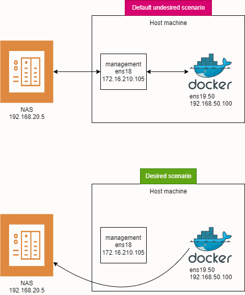
When you have only one interface connected and you add another interface to the same machine (in my case VLAN interface), there will be 2 default routes: one for each interface, in my test lab ens18 and ens19.50. Both will initially have a default route metric of 100. The metric is a measure of route priority, where a higher metric means lower priority.
ens18 will be used for server management and ens19.50 will be used for qBittorent Docker container. I want to mount a NAS share to the host, to which a qBittorent Docker container would have access to. Because both routes have the same metric, we don’t know from which interface a samba share would be mounted. I don’t want my samba share to be mounted via management interface, because all traffic from torrents to NAS will go through management interface, and we don’t want that. Firstly ens18 is only 1 Gbps while ens19.50 is 10 Gbps and secondly, traffic flow from ens19.50 to ens18 is forbidden on my firewall, so Docker container wouldn’t be able to save files.
Tested on Ubuntu server 24.04 LTS.
Goals:
- ens18: Used for server management.
- ens19.50: Used for a qBittorrent Docker container.
- Mount a NAS share to the host, accessible by the qBittorrent Docker container directly.
Problem:
With both routes having the same metric, the system might mount the Samba share via the ens18 management interface. This is not desirable because:
- Bandwidth Limitation:
ens18is only 1 Gbps, whileens19.50is 10 Gbps. - Firewall Restrictions: Traffic flow from
ens19.50toens18is forbidden on my firewall, preventing the Docker container from saving files to the NAS if it were mounted viaens18. That means, torrent traffic would flow fromens19.50to NAS viaens18, because samba share is mounted viaens18.
Solution:
To ensure that traffic to the NAS goes through the 10 Gbps ens19.50 interface, we will:
- Change the Metric: Adjust the metric for the default route on
ens19.50to 200, making it a lower priority for general traffic. - Add a Specific Route: Add a specific route for the NAS (192.168.20.5) via
ens19.50.
Network Configuration:
- ens18: untagged interface (management)
- IP: 172.16.210.105
- Mask: 255.255.255.0
- Gateway: 172.16.210.1
- ens19.50: created on trunk interface (VLAN50 – torrent traffic)
- IP: 192.168.50.100
- Mask: 255.255.255.0
- Gateway: 192.168.50.1
- Docker network type is macvlan
- NAS server: (torrent flow destination)
- IP: 192.168.20.5
Ens18 and ens19.50 both receive their IP configuration via DHCP server. I prefer creating static DHCP reservation on my firewall than entering IPs manually to each device.
Steps:
- Understand Route Metrics:
- Each route has a metric.
- Lower metric means higher priority.
- We will change the metric of the default route for
ens19.50to 200, soens18will be preferred for all traffic except192.168.20.5.
- Edit Netplan Configuration:
- We will edit the netplan configuration to set the route metrics and add a specific route for
192.168.20.5.
- We will edit the netplan configuration to set the route metrics and add a specific route for
Instructions:
- Open the Netplan Configuration File:
- Open a terminal.
- Use a text editor to edit the netplan configuration file
/etc/netplan/vlans.yaml.
- Configure the Interfaces and Routes:
- Add the following configuration:
network:
  version: 2
  ethernets:
    ens19:
      dhcp4: no
    ens18:
      dhcp4: true
  vlans:
    ens19.50:
      id: 50
      link: ens19
      dhcp4: true
      dhcp4-overrides:
        route-metric: 200
      routes:
        - to: 192.168.20.5/32
          via: 192.168.50.1
Explanation:
ethernets: Defines the parent interfaceens19and the primary interfaceens18.vlans: Defines the VLAN interfaceens19.50with VLAN ID 50.dhcp4-overrides: Sets the route metric forens19.50to 200.routes: Adds a specific route for192.168.20.5via192.168.50.1
- Apply the Configuration:
-
- Apply the netplan configuration with the following command:
netplan apply
- Verify the Routing Table:
-
- Check the routing table to ensure the configuration is correct:
ip route
-
- You should see:
default via 172.16.210.1 dev ens18 proto dhcp src 172.16.210.105 metric 100
default via 192.168.50.1 dev ens19.50 proto dhcp src 192.168.50.100 metric 200
192.168.50.1 dev ens19.50 proto dhcp scope link src 192.168.50.100 metric 200
Result:
- Traffic to
192.168.20.5will go viaens19.50(VLAN50). - All Other Traffic: Will go via
ens18because its metric is 100, which has higher priority overens19.50with a metric of 200.
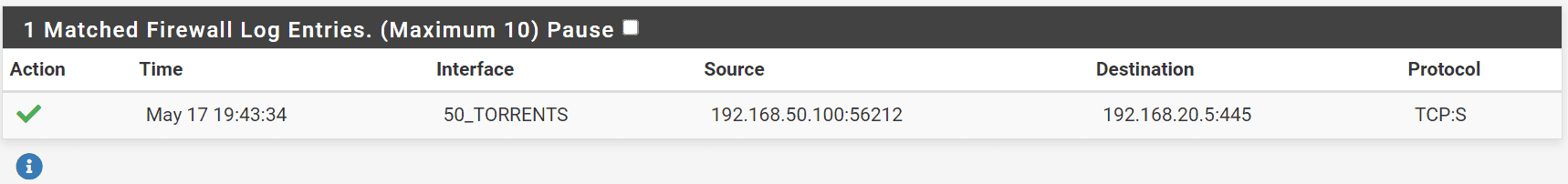
When we mount the share, we can see in our pfsense firewall, the connection was successfully established from 192.168.50.100 (ens19.50) to 192.168.20.5 (NAS)
Notes:
- The
dhcp4-overridessection in the netplan file allows you to specify DHCP options, including setting the route metric. - Specific routes added in the
routessection ensure that traffic to192.168.20.5uses the desired interface.
What is Policy-Based Routing?
Policy-based routing (PBR) is a technique used to make routing decisions based on policies set by network administrators. These policies can be based on various criteria such as source or destination IP addresses, protocols, or traffic types. In this example, we are using PBR to route traffic to a specific IP address (192.168.20.5) through a specific interface (ens19.50).