Scenario:

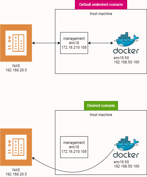
When you have only one interface connected and you add another interface to the same machine (in my case VLAN interface), there will be 2 default routes: one for each interface, in my test lab ens18 and ens19.50. Both will initially have a default route metric of 100. The metric is a measure of route priority, where a higher metric means lower priority.

ens18 will be used for server management and ens19.50 will be used for qBittorent Docker container. I want to mount a NAS share to the host, to which a qBittorent Docker container would have access to. Because both routes have the same metric, we don’t know from which interface a samba share would be mounted. I don’t want my samba share to be mounted via management interface, because all traffic from torrents to NAS will go through management interface, and we don’t want that. Firstly ens18 is only 1 Gbps while ens19.50 is 10 Gbps and secondly, traffic flow from ens19.50 to ens18 is forbidden on my firewall, so Docker container wouldn’t be able to save files.

Tested on Ubuntu server 24.04 LTS.

Goals:

  • ens18: Used for server management.
  • ens19.50: Used for a qBittorrent Docker container.
  • Mount a NAS share to the host, accessible by the qBittorrent Docker container directly.

Problem:

With both routes having the same metric, the system might mount the Samba share via the ens18 management interface. This is not desirable because:

  1. Bandwidth Limitation: ens18 is only 1 Gbps, while ens19.50 is 10 Gbps.
  2. Firewall Restrictions: Traffic flow from ens19.50 to ens18 is forbidden on my firewall, preventing the Docker container from saving files to the NAS if it were mounted via ens18. That means, torrent traffic would flow from ens19.50 to NAS via ens18, because samba share is mounted via ens18.

Solution:

To ensure that traffic to the NAS goes through the 10 Gbps ens19.50 interface, we will:

  1. Change the Metric: Adjust the metric for the default route on ens19.50 to 200, making it a lower priority for general traffic.
  2. Add a Specific Route: Add a specific route for the NAS (192.168.20.5) via ens19.50.

Network Configuration:

  • ens18: untagged interface (management)
    • IP: 172.16.210.105
    • Mask: 255.255.255.0
    • Gateway: 172.16.210.1
  • ens19.50: created on trunk interface (VLAN50 – torrent traffic) 
    • IP: 192.168.50.100
    • Mask: 255.255.255.0
    • Gateway: 192.168.50.1
    • Docker network type is macvlan
  • NAS server: (torrent flow destination)
    • IP: 192.168.20.5

Ens18 and ens19.50 both receive their IP configuration via DHCP server. I prefer creating static DHCP reservation on my firewall than entering IPs manually to each device.

Steps:

  1. Understand Route Metrics:
    • Each route has a metric.
    • Lower metric means higher priority.
    • We will change the metric of the default route for ens19.50 to 200, so ens18 will be preferred for all traffic except 192.168.20.5.
  2. Edit Netplan Configuration:
    • We will edit the netplan configuration to set the route metrics and add a specific route for 192.168.20.5.

Instructions:

  1. Open the Netplan Configuration File:
    • Open a terminal.
    • Use a text editor to edit the netplan configuration file /etc/netplan/vlans.yaml.
  2. Configure the Interfaces and Routes:
    • Add the following configuration:

network: version: 2 ethernets: ens19: dhcp4: no ens18: dhcp4: true vlans: ens19.50: id: 50 link: ens19 dhcp4: true dhcp4-overrides: route-metric: 200 routes: - to: 192.168.20.5/32 via: 192.168.50.1

Explanation:

  • ethernets: Defines the parent interface ens19 and the primary interface ens18.
  • vlans: Defines the VLAN interface ens19.50 with VLAN ID 50.
    • dhcp4-overrides: Sets the route metric for ens19.50 to 200.
    • routes: Adds a specific route for 192.168.20.5 via 192.168.50.1
  1. Apply the Configuration:
    • Apply the netplan configuration with the following command:

netplan apply

  1. Verify the Routing Table:
      • Check the routing table to ensure the configuration is correct:

    ip route

      • You should see:

    default via 172.16.210.1 dev ens18 proto dhcp src 172.16.210.105 metric 100 default via 192.168.50.1 dev ens19.50 proto dhcp src 192.168.50.100 metric 200 192.168.50.1 dev ens19.50 proto dhcp scope link src 192.168.50.100 metric 200

    Result:

    • Traffic to 192.168.20.5 will go via ens19.50 (VLAN50).
    • All Other Traffic: Will go via ens18 because its metric is 100, which has higher priority over ens19.50 with a metric of 200.

    When we mount the share, we can see in our pfsense firewall, the connection was successfully established from 192.168.50.100 (ens19.50) to 192.168.20.5 (NAS)

    Notes:

    • The dhcp4-overrides section in the netplan file allows you to specify DHCP options, including setting the route metric.
    • Specific routes added in the routes section ensure that traffic to 192.168.20.5 uses the desired interface.

    What is Policy-Based Routing?

    Policy-based routing (PBR) is a technique used to make routing decisions based on policies set by network administrators. These policies can be based on various criteria such as source or destination IP addresses, protocols, or traffic types. In this example, we are using PBR to route traffic to a specific IP address (192.168.20.5) through a specific interface (ens19.50).
    Starting with version 8.5, Cisco has introduced an innovative feature to its Wireless LAN Controller (WLC): the Identity Pre-Shared Key, or iPSK. This functionality allows multiple devices, especially those unable to support WPA Enterprise authentication (802.1x), to connect to the same SSID but with unique credentials and configurations. This can be particularly useful in diverse device environments, such as those involving various IoT devices.

    A common application of iPSK includes setting up distinct network access configurations for different devices on the same network. Here are two practical scenarios:

    Scenario 1: All devices connect to the same SSID using the same Wi-Fi password, yet they are assigned to different VLANs based on their identity.

    Scenario 2: Devices connect to the same SSID with distinct Wi-Fi passwords, and can either be on the same VLAN or separate VLANs depending on the configuration.

    While Scenario 1 is ideal for simplicity and home networks, may not offer the same level of security as Scenario 2. It is perfectly suited for home networks where the primary goal is to segment devices into different VLANs using the same password. This setup simplifies management without significantly compromising security, making it a practical choice for less complex environments.

    Scenario 2 is the optimal security configuration and offers the highest level of security. In this setup, each device is assigned its own unique password. This is particularly beneficial because if a device is compromised, the impact is isolated. You only need to revoke or change the password for the affected device without disrupting the connectivity of other devices on the network.

    Before diving into the specific scenarios of iPSK deployment, ensure you have the following foundational elements configured and operational:

    – WLC Controller and pfSense RADIUS Server Connection: Ensure that your Wireless LAN Controller (WLC) and pfSense RADIUS server are properly connected and communicating. This setup is crucial for authenticating devices on your network using iPSK.

    – VLAN Functionality: Configure VLANs on both the pfSense and WLC controller. On the pfSense, this involves setting up VLAN tagging and defining VLAN interfaces. On the WLC controller, VLANs should be configured under the ‘Interfaces’ section. Proper VLAN configuration is essential for segmenting network traffic and enhancing security.

    Having these elements in place will provide a solid foundation for implementing the iPSK scenarios described, ensuring a smoother and more secure deployment.

    My lab setup was done on Cisco WLC 2504 (8.5.105.0) and PfSense (2.7.2).

    Setting Up Scenario 1: Single Password with VLAN Assignment on the same SSID

    To configure iPSK with VLAN assignments using the same password for all devices, follow these steps on your pfSense and WLC controller:

    1 Configure Users in pfSense:

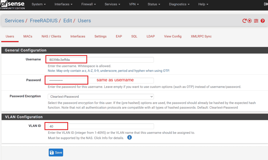
    • Navigate to Services -> FreeRADIUS -> Users on your pfSense interface.
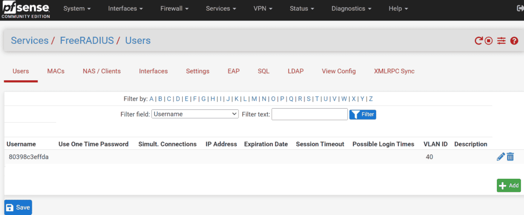
    • Create a new user entry where both the username and password are the MAC address of the client device, formatted without separators. For instance, if the MAC address is 80:39:8c:3e:ff:da, you would use 80398c3effda for both the username and password. If you’re using Android clients, make sure you disable randomize MAC option in wifi settings and use Phone MAC instead.

    2 Assign VLANs:

    • When creating the user, also assign the desired VLAN to this username. This VLAN is where the device will be placed upon successful authentication.


    3. configure WLAN in WLC for scenario 1:

    To set up the WLAN that will be used with iPSK, follow these detailed steps within your Cisco Wireless LAN Controller (WLC):

    3.1 Create a New WLAN:

    • Navigate to the WLANs section in the WLC interface.
    • Click on Create New WLAN to start the setup process.

    3.2 General Settings:

    • In the General tab, provide a Profile Name and the SSID (Service Set Identifier) for your new WLAN.
    • Make sure to set the WLAN status to Enabled to activate it upon creation.

    3.3 Security Settings:

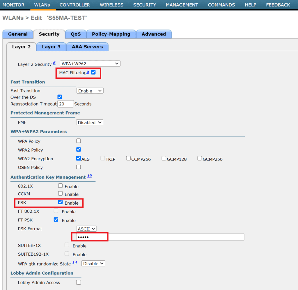
    • Go to the Security tab and then to the Layer 2 sub-tab.
    • Enable MAC Filtering to restrict access based on the MAC addresses of client devices.
    • Additionally, enable the PSK (Pre-Shared Key) option to set a universal Wi-Fi password for all devices. Directly beneath the PSK settings, enter the Wi-Fi password you desire in the PSK Format field.

    3.4 Radius server

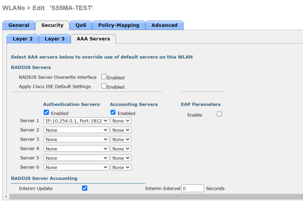
    • Go to the security tab and then to the AAA Server sub-tab
    • Under Server 1, select your radius server, which should be already set from required prerequisites
    • Apply settings and try to connect the client

    3.5 Advanced settings

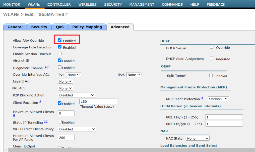
    • Go to Advanced tab and enable Allow AAA Override. This means, radius server will push settings like VLAN, QOS and other optional stuff.

    Authentication workflow in scenario 1 is:

    • When a client attempts to connect to the Wi-Fi network, the WLC will initially check the Wi-Fi universal password (PSK).
    • After the PSK validation, the WLC will forward the authentication request to the pfSense RADIUS server to verify if the client’s MAC address matches the username and password configured in RADIUS.
    • If a match is found, the user is authorized and placed into the correct VLAN. If no matching user entry exists for the MAC address, the Wi-Fi connection attempt will fail.
    • If the VLAN specified for a client in the pfSense RADIUS server does not exist on the Cisco WLC, or if it is not properly configured in the WLC settings, the client device will not be assigned to the intended VLAN. Instead, the device will default to the VLAN associated with the WLC’s default interface for that particular WLAN.

    Setting Up Scenario 2: Unique Passwords with VLAN Assignment on the same SSID

    This scenario allows each user to have a unique password, enhancing security by isolating potential breaches to individual devices. Follow these steps to configure unique passwords per user in pfSense using FreeRADIUS:

    2.1 Edit User Configuraton:

    • Navigate to Services -> FreeRADIUS -> Users in the pfSense interface.
    • Select and edit the user configuration set up in Scenario 1.

    2.2 Configure Additional RADIUS Attributes:

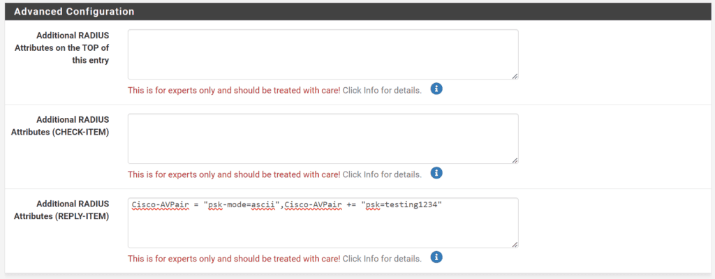
    • Scroll to the bottom of the user settings to find the field labeled Additional RADIUS Attributes (REPLY-ITEM).
    • Add Cisco AV Pairs to define unique passwords for each device
    • Enter Cisco-AVPair = “psk-mode=ascii” to specify that the password is in plain text.
    • Add Cisco-AVPair += “psk=client_unique_wifi_cleartext_password” where client_unique_wifi_cleartext_password is the unique password you assign to this user. Replace client_unique_wifi_cleartext_password with the actual password you intend to use.
    • The whole entry should look like: Cisco-AVPair = “psk-mode=ascii”,Cisco-AVPair += “psk=client_unique_wifi_cleartext_password”

    2.3 Save the configuration

    2.4 Connect to the Network

    • Attempt to connect a device using the new unique password set in the RADIUS attributes.
    • Ensure that the device’s MAC address randomization feature is turned off to avoid connection issues due to unrecognized MAC addresses.

    Authentication workflow in scenario 2 is:

    • When a client attempts to connect to the Wi-Fi network with Radius password, the WLC will forward the authentication request to Radius to validate user.
    • If a match is found, the user is authorized and placed into the correct VLAN. If no matching user entry exists for the MAC address, the Wi-Fi connection attempt will fail.
    • If the VLAN specified for a client in the pfSense RADIUS server does not exist on the Cisco WLC, or if it is not properly configured in the WLC settings, the client device will not be assigned to the intended VLAN. Instead, the device will default to the VLAN associated with the WLC’s default interface for that particular WLAN.

    Steps to configure fallback VLAN in FreeRADIUS on PfSense:

    In both Scenario 1 and Scenario 2, you need to have a valid RADIUS user. If you try to use the universal WiFi password defined in the WLC, it won’t work. To use a fallback VLAN with a universal password for users not defined in RADIUS, you need to add additional parameters in the FreeRADIUS configuration. SSH into your pfSense system and open the file at /usr/local/etc/raddb/users.

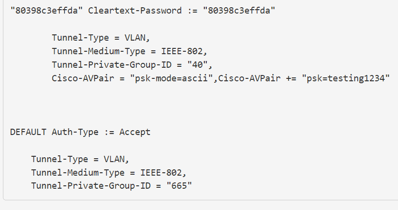
    Add this to the end of the file:

    DEFAULT Auth-Type := Accept
    
        Tunnel-Type = VLAN,
        Tunnel-Medium-Type = IEEE-802,
        Tunnel-Private-Group-ID = "665"

    Change “665” to your desired fallback VLAN. Save the file and restart the Radius server. Ensure that this entry is always at the end of the file when adding new users.

    In your PfSense GUI, it should look something like this:

    Now, you can connect a device without a RADIUS user to the WiFi using the universal password. It will default to VLAN 665.

    Caveat: editing config files directly from shell is tricky for PfSense, because everytime you change a config via GUI, config edite from shell will get rewritten, and all your changes will be gone. The same will happen with reboot. If you wan’t to make a change permanent, you should make a cronjob that adds manual config at reboot, or edit main template file radius.inc found at /usr/local/pkg/freeradius.inc.

    Example:

    • Connecting with a user defined in RADIUS will result in a successful connection to WiFi with the VLAN assigned to that user.
    • Connecting to WiFi with the universal password will result in a successful connection with the VLAN defined under DEFAULT Auth-Type := Accept, in this case, VLAN 665.

    You can use both WLC universal password and radius user password to connect to WiFi, depending on your needs. Ensure your fallback VLAN is securely configured.

    References:
    https://www.linkedin.com/pulse/shared-ssid-ciscos-identity-psk-freeradius-alexandru-panaitescu/
    https://www.wifireference.com/2017/12/10/cisco-identity-psk-what-is-it-and-how-is-it-configured/
    https://www.cisco.com/c/en/us/support/docs/security-vpn/remote-authentication-dial-user-service-radius/116291-configure-freeradius-00.html
    https://goodwi.fi/posts/2023/09/ipsk-no-ise-freeradius/