Docker by default uses networks from 172.17.0.0/16 private range. This can sometimes conflicts with network you already have in your network environment. This will cause routing problems when clients from the same network subnets will try to access Docker services. In this case, Docker will route packets to containers instead back to clients.

To solve this, you need to define unused subnets and assign it to Docker. You can do this with daemon.json file.

Edit file (it if doesn’t exist, create it):

nano /etc/docker/daemon.json

Add this and edit to your needs:

{
  "bip": "172.17.192.1/26",
  "default-address-pools": [
    {
      "base": "172.17.192.64/28",
      "size": 29
    }
  ]
}

“bip”: “172.17.192.1/26” – This will be used for docker0 interface
“base”: “172.17.192.64/28” – This will be used for container bridges
“size”: 29 – Subnet prefix, means how large is going to be each bridge

Save file and restart docker:

service docker restart

In case you used docker-compose, first delete networks and containers with:

docker-compose down

In case you have more old bridges, list them with:

docker network ls

and delete with:

docker network rm network_name

or delete all networks with:

docker network prune

Alternatively, use a portion ob public network that you’re never going to use, for example:

{
  "bip": "100.100.100.1/26",
  "default-address-pools": [
    {
      "base": "100.100.100.64/28",
      "size": 29
    }
  ]
}

Or use host networking, this will bind container network directly to host. But you will lose container isolation with this method: https://docs.docker.com/network/host/

New unboxed Cisco ISR4331, command configure terminal didn’t work. Looks like the router is booted in controller mode by default. To get back to “legacy” mode you need to disable controller mode.

Router#conf t
This command is not supported
Router# controller-mode disable
Disabling controller mode will erase the nvram filesystem, remove all configuration files, and reload the box!
Ensure the BOOT variable points to a valid image
Continue? [confirm]
% Warning: Bootstrap config file needed for Day-0 boot is missing
Do you want to abort? (yes/[no]): no
 Mode change success

Wait a few minutes, router will reload.

Router>en
Router#conf t
Enter configuration commands, one per line.  End with CNTL/Z.
Router(config)#

Whenever you update Cisco DNA center, backups stop working. You need to re-apply NFS configuration in DNA center GUI which will restart the docker container and enable backups again.

For example, delete one slash in the Server Path option, write it back and apply. Wait a few minutes for the Docker process to restart. Backups should work now.

I added an extra network card to my Proxmox server (Mellanox Connect-X3) and some VLANs were not working. It turned out Mellanox Connect-X3 supports only about 128 VLANS in memory. Proxmox by default adds VLANs from 2-4094. You can see it in /etc/network/interfaces, line bridge-vids 2-4094.

When you try to reload networking from console, you get this error:

root@proxmox:~# ifreload -a
error: enp1s0: failed to set vid `{2,...4094}` (cmd '/sbin/bridge vlan add vid 2-4094 dev enp1s0' 
failed: returned 255 (RTNETLINK answers: No space left on device))

To fix this, open /etc/network/interfaces and add only VLANs you need. For example:

Original:

auto vmbr1
iface vmbr1 inet manual
        bridge-ports enp1s0
        bridge-stp off
        bridge-fd 0
        bridge-vlan-aware yes
        bridge-vids 2-4094

Fixed:

auto vmbr1
iface vmbr1 inet manual
        bridge-ports enp1s0
        bridge-stp off
        bridge-fd 0
        bridge-vlan-aware yes
        bridge-vids 20,21,30,40,50,60,90,200,210,254,600,664-668

Restart networking:

ifreload -a

Assign VLANs to your VMs now, it should work.

EDIT: they fixed their official documentation

Official Cisco documentation about setting up NFS server for DNA center is here. The problem is, this is for Ubuntu, and Ubuntu has different names for group “nobody” than CentOS.

So if you get an error saying:

BACKUP.ndp:elasticsearch
FAILURE
Exception
Task error description:
Error during _process_backup(): Internal server error: {"error":{"root_cause":[{"type":"snapshot_creation_exception",
"reason":"[ndp:e522e20b-69e3-45b0-b20c-20138ba1444c.000/AGvhN1eCRH6CtE60mNl3KA] failed to create snapshot"}],"type":"
snapshot_creation_exception","reason":"[ndp:e522e20b-69e3-45b0-b20c-20138ba1444c.000/AGvhN1eCRH6CtE60mNl3KA] failed to
create snapshot","caused_by":{"type":"access_denied_exception","reason":"/var/data/es/snapshots/meta-AGvhN1eCRH6CtE60mNl3KA.dat"}},"status":500}

That means you have the wrong user and group set up on server NFS directory.

For Ubuntu:

chown nobody:nogroup /dir/to/nfs/share

For CentOS:

chown nfsnobody:nfsnobody /dir/to/nfs/share

Prerequisites:

– raspbian OS
– CA cert, client cert and cert password, client key

You can use .p12 file and convert it to .pem, it will include client cert and client key in the same file. Let’s say you download .p12 file from PfSense cert manager. Convert it with:

openssl pkcs12 -in test.p12 -out test.pem
Enter Import Password: leave empty
Enter PEM pass phrase: testing1234
Verifying - Enter PEM pass phrase: testing1234

First, delete openresolv and dhcpcd5 because it’s conflicting with native network management:

apt purge openresolv dhcpcd5

Disable wpa_supplicant:

systemctl disable wpa_supplicant

Install nmcli:

apt install network-manager

Comment out everything in /etc/network/interfaces and in /etc/wpa_supplicant/wpa_supplicant.conf and then Reboot Pi

Create wifi connection:

nmcli c add type wifi ifname wlan0 con-name "My-Wifi" \
      802-11-wireless.ssid "WIFI-SSID" \
      802-11-wireless-security.key-mgmt wpa-eap \
      802-1x.eap tls \
      802-1x.identity test \
      802-1x.ca-cert /home/pi/CA.crt \
      802-1x.client-cert /home/pi/test.pem \
      802-1x.private-key /home/pi/test.pem \
      802-1x.private-key-password testing1234

Depending on the network-manager version, the commands above might not work, so just enter it manually line by line:

nmcli con add type wifi ifname wlan0 con-name My-Wifi ssid WIFI-SSID
nmcli con edit id wifi
nmcli> set 802-11-wireless.ssid WIFI-SSID
nmcli> set 802-11-wireless-security.key-mgmt wpa-eap
nmcli> set 802-1x.eap tls
nmcli> set 802-1x.identity test
nmcli> set 802-1x.ca-cert /home/pi/CA.crt
nmcli> set 802-1x.client-cert /home/pi/test.pem
nmcli> set 802-1x.private-key-password testing1234
nmcli> set 802-1x.private-key /home/pi/test.pem
nmcli> save
nmcli> quit

Check connection with:

nmcli connection
NAME                UUID                                  TYPE      DEVICE
My-Wifi             f0c28a28-934f-4dbc-823f-b3c1653bb047  wifi      wlan0

Start connection:

nmcli connection up My-Wifi

If you want to start over, you can delete connection with:

nmcli connection delete My-Wifi

You can also view and edit profile at /etc/NetworkManager/system-connections/My-Wifi.nmconnection

cat /etc/NetworkManager/system-connections/My-Wifi.nmconnection
[connection]
id=My-Wifi
uuid=f0c28a28-934f-4dbc-823f-b3c1653bb047
type=wifi
interface-name=wlan0
permissions=

[wifi]
mac-address-blacklist=
mode=infrastructure
ssid=WIFI-SSID

[wifi-security]
key-mgmt=wpa-eap

[802-1x]
ca-cert=/home/pi/CA.crt
client-cert=/home/pi/test.pem
eap=tls;
identity=test
private-key=/home/pi/test.pem
private-key-password=testing1234

[ipv4]
dns-search=
method=auto

[ipv6]
addr-gen-mode=stable-privacy
dns-search=
method=auto

We are going to install Cisco wireless virtual controller on Proxmox hypervisor and connect it to pfSense router.

Prerequisites:

  • pfSense router with required VLANS created and tagged to Proxmox (I will not cover how to setup VLANs on pfSense)
  • VLAN capable switch
  • Cisco access point
  • Proxmox hypervisor
  • vWLC iso file (you can get it from Cisco support site if you have a service contract, otherwise search the internet, hint: torrents (CTVM)). Check your access points models and see which vWLC supports your access points. In my case, I want to support some older APs so I installed version 8.3.150. I recommend you to install 8.5.x.

1. Create a new virtual machine in Proxmox
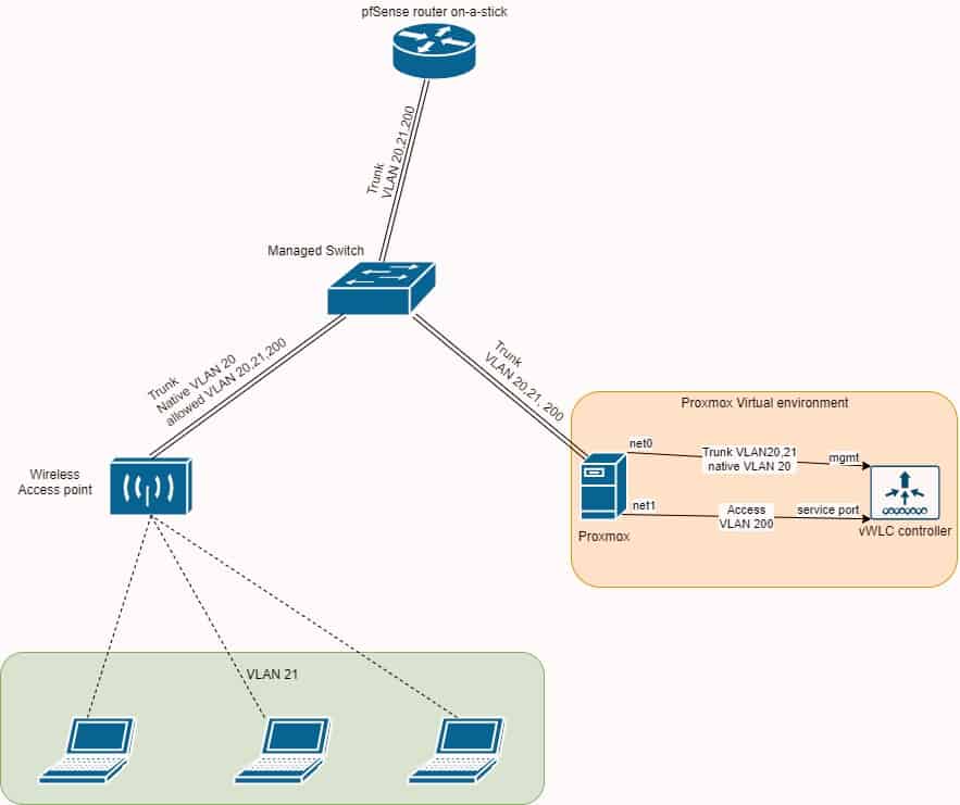
vWLC requires two network interfaces, one for management and one for out of band (OOB) service port. Management interface has to be a trunk (tagged) port (carrying multiple vlans). Service port has to be an access port only (untagged). Let’s say we will use VLAN 20 for management, VLAN 200 for service ports and VLAN 21 for wifi users. Before creating interfaces in vWLC virtual machine, make sure your Proxmox bridges are VLAN aware.

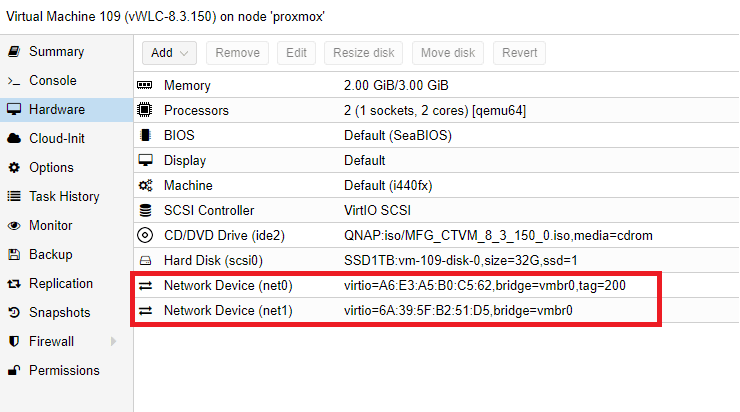
2. Create a new VM and add two interfaces.
First interface should be tagged with service-port VLAN, in  my case VLAN 200. The second interface should have no tag, that means it’s a trunk port (it can carry multiple VLANS).

3. Start up newly created VM with loaded vWLC ISO and begin installation
You will be asked to enter:

– service port interface IP (you can use DHCP or static, this is a tagged/access port interface, with VLAN 200 in my case)
– management interface IP (this is a trunk interface, but it will ask you for a vlan tag that will become native vlan for this interface … Tag it, in my case VLAN 20, it needs to be static IP address, set it to IP address scheme that reflects your VLAN, in my case VLAN 20)
– NTP server
– credentials

After installation is complete, you should be able to access vWLC webGUI via https://management_interface_IP_on_VLAN20

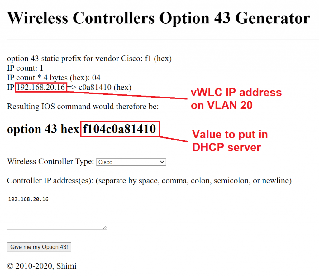
4. Access point provisioning, DHCP option 43
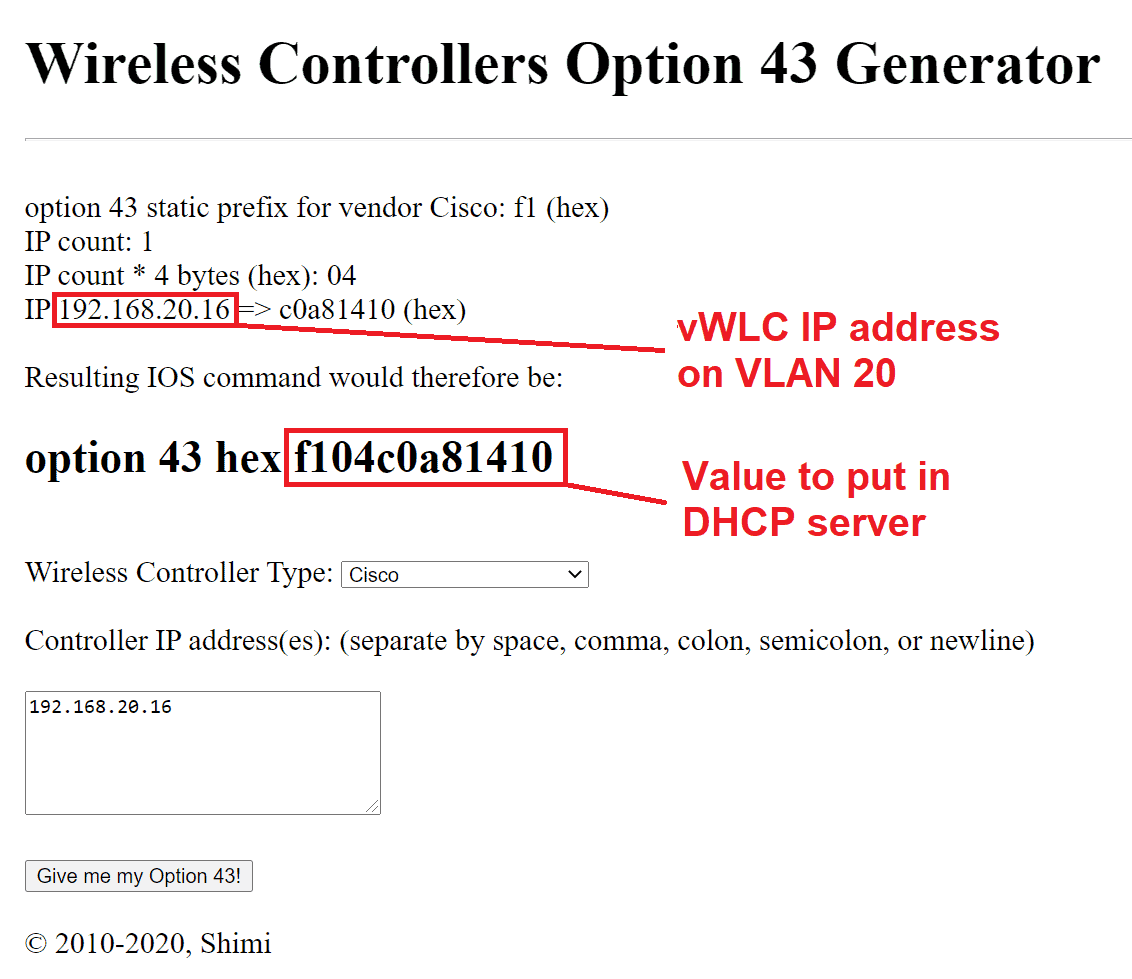
It will happen on management interface vlan, in my case VLAN 20. APs will need to know the IP of the vWLC controller, so we need to setup option 43 in our DHCP server that’s running on pfSense. Option 43 will tell access point the IP of the vWLC controller. You can help yourself with an option 43 generator (https://shimi.net/services/opt43/). More detailed guide from Cisco concerning option 43 is here: https://community.cisco.com/t5/wireless-mobility-documents/configuring-dhcp-option-43-and-option-60/ta-p/3143572


Optionally, you can also add option 60 (VCI – Vendor Class Identifier). You can get APs VCIs here: https://www.cisco.com/c/en/us/support/docs/wireless-mobility/wireless-lan-wlan/97066-dhcp-option-43-00.html#anc5

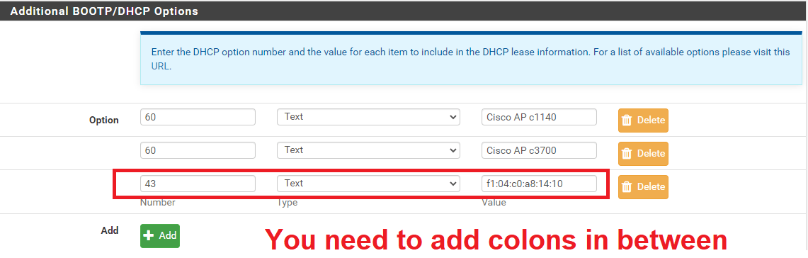
Go to pfSense -> Services -> DHCP Server -> VLAN20 -> Additional BOOTP/DHCP Options -> Display Advanced


Save and apply changes.

EDIT: option 43 should be type string, not text!

5. Switch settings
vWLC supports only Flexconnect mode, that means you need to setup your switch ports (where APs will be connected to it) as a trunk port and setup a native VLAN. For non Cisco terms: untagged + tagged ports. Native VLAN should be the same as management interface, in my case VLAN 20. Trunk should also carry VLAN 21 for wifi clients.

Example for cisco:

interface GigabitEthernet1/0/1
switchport trunk native vlan 20
switchport trunk allowed vlan 20,21
switchport mode trunk

Other vendors have tagging and untagging, so VLAN 20 untagged, VLAN 21 tagged.

6. Connect AP to configured switch port
Connect AP to the switch and wait a few minutes to join the controller. If AP doesn’t join, check logs on WLC controller: MANAGEMENT -> Logs -> Message logs

If you get: (5246) Regulatory Domain Mismatch

Means you have to change country code to match the AP (usually US):

Shutdown radios first:

WLC GUI -> Wireless -> 802.11a/n/ac -> Network -> 802.11a Network Status (untick Enabled and apply)
WLC GUI -> Wireless -> 802.11b/g/n -> Network -> 802.11a Network Status (untick Enabled and apply)

Change country:

WLC GUI -> WIRELESS -> Country -> Tick US and apply

Reenable radios now.

Sometimes AP still won’t join, especially old ones. If you connect AP to a console cable and watch a console, you might get someting like:

*Oct 7 18:44:58.000: %CAPWAP-5-DTLSREQSEND: DTLS connection request sent peer_ip: 192.168.20.16 peer_port: 5246
*Oct 7 18:44:58.477: %DTLS-5-ALERT: Received FATAL : Certificate unknown alert from 192.168.20.16
*Oct 7 18:44:58.477: %DTLS-5-SEND_ALERT: Send FATAL : Close notify Alert to 192.168.20.16:5246

This means the certs on AP are expired. You can disable this by SSH into vWLC controller and enter the following commands:

config ap cert-expiry-ignore mic enable
config ap cert-expiry-ignore ssc enable

7. Enable SSID broadcasting
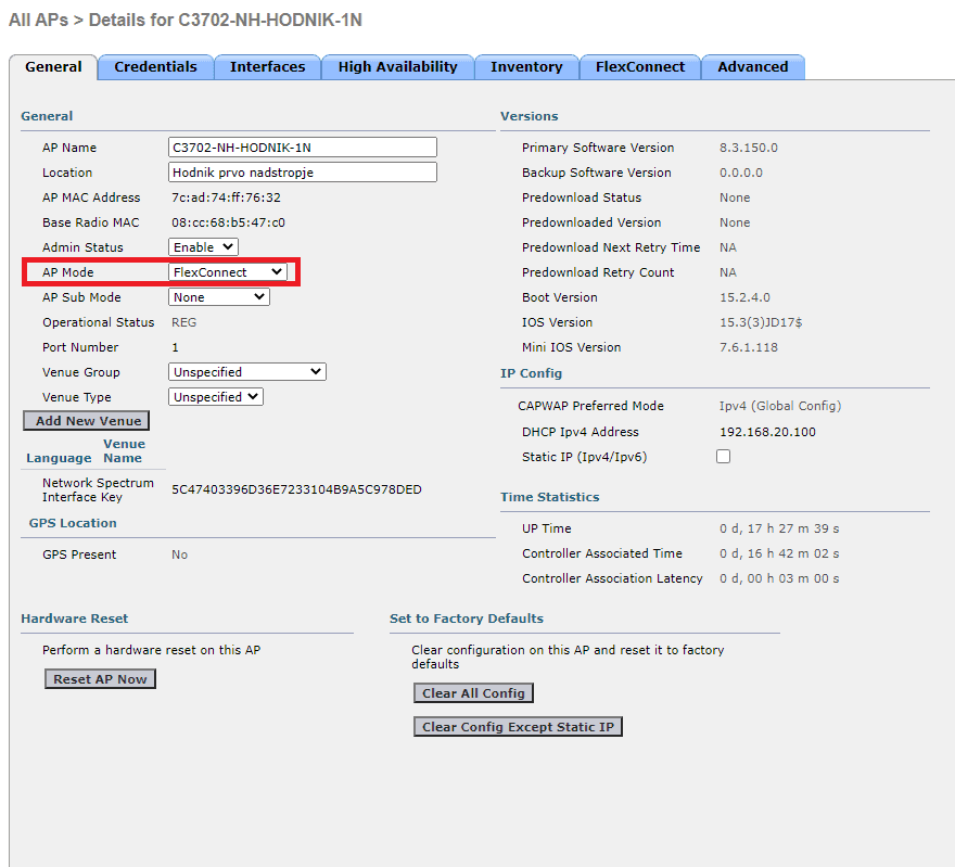
vWLC supports only Flexconnect, so we need to enable it:

Go to WLC GUI -> WIRELESS -> Access Points -> All APs -> select AP from the list -> AP Mode -> FlexConnect and apply

8. Create wireless network
First you need to create VLAN interface for wifi clients.

Go to WLC GUI -> Controller -> Interfaces -> New -> Interface name: vlan21 -> VLAN Id: 21 -> Apply

Now create WLAN network

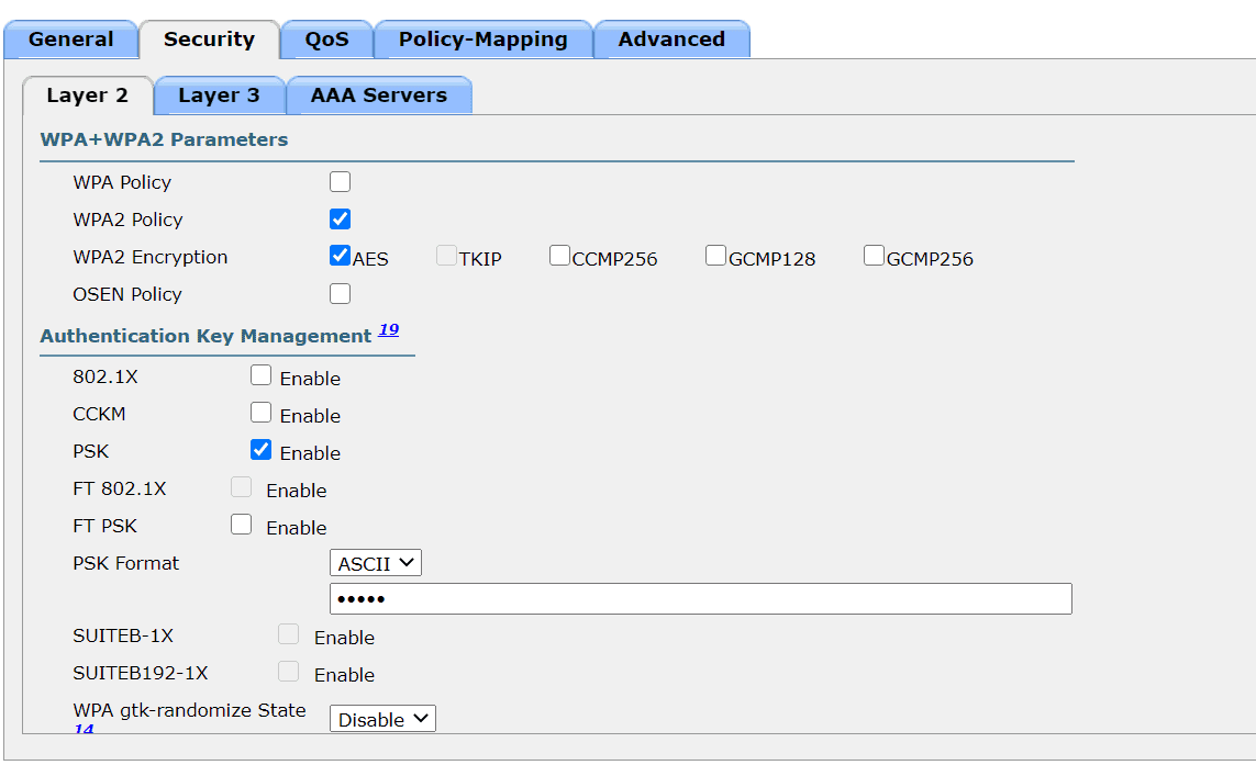
Go to WLC GUI -> WLANs -> Create new -> Enter Profile Name and SSID -> tick Status enabled and select Interface/Interface Group(G) vlan21 -> go to Security -> Layer 2 -> scroll down -> tick PSK Enable and create a wifi password -> Apply

9. Enable VLANs on AP
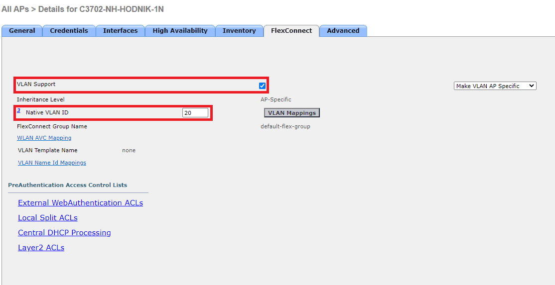
You need to setup native VLAN (in my case VLAN 20) on APs and add WLAN-VLAN mappings.

Go to WLC GUI -> WIRELESS -> Access Points -> All APs -> select AP from the list -> FlexConnect, tick VLAN support and enter native VLAN:

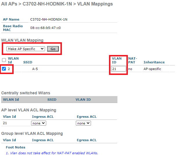
Next click on VLAN Mappings. Tick SSID under WLAN id, enter wifi clients VLAN under VLAN ID (in my case VLAN 21) and click Go at section Make AP specific.

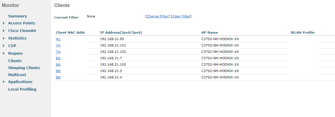
10. You wifi clients should be able to connect now

11. 60 days trial license

There is a 60 days trial license, but you can enable RTU (right to use) license that will not expire (note: this is against cisco TOS).

Go to WLC GUI -> MANAGEMENT -> Software Activation -> Licenses -> license count: custom number -> Set Count -> Accept EULA and you are done.

12. Quick topology drawing

Adding CIFS storage from GUI fails with error message:

create storage failed: error during cfs-locked 'file-storage_cfg' operation: mount error: Refer to the mount.cifs(8) manual page (e.g. man mount.cifs) (500)

We will add share via CLI, because you need to include smbversion 2.1:

pvesm add cifs <PROXMOX_NEW_VOLUME_NAME> --server <QNAP_IP> --share <SHARED_FOLDER_ON_QNAP> --username <QNAP_CIFS_SHARE_USERNAME> --password <QNAP_CIFS_SHARE_PASSWORD> --smbversion 2.1

Example:

pvesm add cifs QNAP --server 10.10.1.1 --share Proxmox --username proxmox --password proxmox.pass --smbversion 2.1

Share is now mounted.

Go to the GUI:

Datacenter -> Storage -> QNAP -> Edit -> Content -> Select the content you want and click OK.

Bitwarden_rs will not work on Chrome without SSL, so we are going to create a self signed certificate. If you are going to host Bitwarden on the internet (outside your local network), use certbot instead.

Prerequisites: working Docker installation on Linux

As sudo or root, make persistent data directories for SSL and Bitwarden files on the Docker host machine:

mkdir -p /docker_data/bitwarden/ssl
cd /docker_data/bitwarden/ssl

Generate certificate and a key.
You will be asked to enter cert data, enter whatever you wan’t, it doesn’t really matter since it’s self signed:

openssl req -x509 -newkey rsa:4096 -keyout bitwarden.key \
-out bitwarden.crt -days 720 -nodes

Start the container, wait until container starts and then go to https://yourdockerhost

docker run -d --restart always --name bitwarden -e \
ROCKET_TLS='{certs="/ssl/bitwarden.crt",key="/ssl/bitwarden.key"}' \
-v /docker_data/bitwarden/ssl/:/ssl/ -v \
/docker_data/bitwarden/:/data/ -p 443:80 bitwardenrs/server:latest

You can check container status with “docker ps”:

docker ps

Output:

Login to Bitwarden wegbui via self signed SSL now.

Tested on 3702 AP.

Hold mode button and turn on the power. Release the mode button when the LED lights amber. Connect the console cable from PC to AP and connect to it via Putty or any other client that supports serial connections.

If necessary delete some old files first to free some space:

ap: dir flash:
ap: delete flash:ap3g2-k9w7-mx.153-3.JPJ3a/ap3g2-k9w7-mx.153-3.JPJ3a
ap: you sure you want to delete "flash:ap3g2-k9w7-mx.153-3.JPJ3a/ap3g2-k9w7-mx.153-3.JPJ3a" (y/n)?y
File "flash:ap3g2-k9w7-mx.153-3.JPJ3a/ap3g2-k9w7-mx.153-3.JPJ3a" deleted
ap: delete flash:private-multiple-fs
ap: you sure you want to delete "flash:private-multiple-fs" (y/n)?y
File "flash:private-multiple-fs" deleted

On AP, configure temporary network settings, so you can upload new firmware over network later.

ap: set IP_ADDR 192.168.0.1
ap: set NETMASK 255.255.255.0
ap: set DEFAULT_ROUTER 192.168.0.1
ap: tftp_init
tftp_init success: You can now use tftp file system!
ap: ether_init
Ethernet speed is 1000 Mb - FULL duplex

Set up your TFTP server (usually laptop or a PC) network address to the same subnet as the access point’s in the step above. For this example, set the network card address to:

IP address: 192.168.0.2
Subnet mask: 255.255.255.0

For quick access to network cards settings on Windows, go to start and type ncpa.cpl, press enter.

Connect UTP cable from TFTP server to access point and start your TFTP server with loaded firmware. You can use TFTPD32 on Windows – Download.

Go back to AP console and fetch the firmware from TFTP server:

ap: tar -xtract tftp://192.168.0.2/ap3g2-k9w7-tar.153-3.JPJ3a.tar flash:
extracting info (283 bytes)
ap3g2-k9w7-mx.153-3.JPJ3a/ (directory) 0 (bytes)
extracting ap3g2-k9w7-mx.153-3.JPJ3a/ap3g2-k9w7-mx.153-3.JPJ3a (119277 bytes).........................
ap3g2-k9w7-mx.153-3.JPJ3a/html/ (directory) 0 (bytes)
ap3g2-k9w7-mx.153-3.JPJ3a/html/level/ (directory) 0 (bytes)
ap3g2-k9w7-mx.153-3.JPJ3a/html/level/1/ (directory) 0 (bytes)
extracting ap3g2-k9w7-mx.153-3.JPJ3a/html/level/1/appsui.js (563 bytes)
extracting ap3g2-k9w7-mx.153-3.JPJ3a/html/level/1/back.shtml (512 bytes)
extracting ap3g2-k9w7-mx.153-3.JPJ3a/html/level/1/cookies.js (5032 bytes).
extracting ap3g2-k9w7-mx.153-3.JPJ3a/html/level/1/forms.js (20442 bytes)....
extracting ap3g2-k9w7-mx.153-3.JPJ3a/html/level/1/sitewide.js (17250 bytes)...

Wait a few minutes for the process to finish and set AP to boot from new firmware:

ap: set BOOT flash:/ap3g2-k9w7-mx.153-3.JPJ3a/ap3g2-k9w7-mx.153-3.JPJ3a
ap: boot

NOTE: This is not the only way to do it. Here is another way without going into recovery – rommon mode.

This bash script will utilize a program called expect to retrieve information about access points connected to WLC. Tested on WLC 5500 series. Current version of the script retrieves the following AP data:

– Access point name
– IP address
– Serial number

Data is written into a file in a table form, ready to be exported to Excel for example. It can be easily modified to meet your needs.

#!/bin/bash

# Install expect first
# Ubuntu: apt install expect
# CentOS: yum install expect

# Check if expect is present on the system
 hash expect > /dev/null 2>&1
 return_code=$?
   if [[ $return_code != 0 ]]
    then
       printf "\nExpect is not present on this system\n"
    else

# Get IP, username, password data
 echo -n "Enter IP/hostname of WLC controller: "
 read hostname
 echo -ne '\n'
 echo -n "Enter username: "
 read username
 echo -ne '\n'
 echo -n "Enter SSH password: "
 read -s -e password
 echo -ne '\n'

# Start expect script
 /usr/bin/expect <<EOF

# Set variables, provided from entered data above
 set hostname [lindex $argv 0]
 set username [lindex $argv 1]
 set password [lindex $argv 2]

# Set log output
 log_file -a ./results-AireOS.log

# Announce which device we are working on and at what time
 send_user "\n"
 send_user ">>>>>  Working on $hostname @ [exec date] <<<<<\n"
 send_user "\n"

# Don't log to console, set to 1 for debugging
 log_user 0

# Don't check keys
 spawn ssh -o StrictHostKeyChecking=no $username\@$hostname

# Allow this script to handle SSH connection issues
 expect {
  timeout { send_user "\nTimeout Exceeded - Check Host\n"; exit 1 }
  eof { send_user "\nSSH Connection To $hostname Failed\n"; exit 1 }
  "User: " { send "$username\n" }
        }

# Provide password
 send_user "Establishing connection ...\n"
 expect "Password:"
 send "$password\n"
 send_user "\nConnected, fetching data, please be patient.\n"

# Enter your commands here (for AireOS):
 expect "*>"
 send "config paging disable\n"
 expect "*>"
 send "show access-point-config\n"

# Even with paging disabled, WLC will still prompt us to press any key to continue
# so me create a loop with exp_continue function to press enter (new line)
# on prompt "Press Enter to continue or <ctrl-z> to abort"

 expect {
         "Press Enter to continue or <ctrl-z> to abort" { send "\n"; exp_continue }
         "(Cisco Controller) >" { send "logout\n" }
        }

 expect {
         "Would you like to save them now? (y/N)" { send "N\n" }
         eof
        }
 send_user "\n"
 exit 0
EOF
fi

# Format output from expect script
 output="$(cat ./results-AireOS.log | grep 'AP Name\|AP Serial\|IP Address' | grep -v 'Configuration\|NAT\|Switch\|Fallback' | \
 cut -d '.' -f2- | awk '{ print $2 }'| tr -d '\r' | paste -d ":" - - - | sort -u | sed "1i AP:IP:SERIAL" | column -s: -t)"

# Write final file
 printf "$output" > ./results-AireOS.log
 printf "Finished, results are ready in the log file.\n\n"

On 3700 series, and probably some others, you can only have max two SSIDs on the same VLAN. One SSID per radio on the same VLAN. If you wan’t to have multiple SSIDs per radio, you’ll have to use different VLANs – this is the recommended option.

This is basic setup (wifi only) for home networks with only one VLAN (or access point connected to access port – untagged port). First SSID on 2.4 GHz radio and second SSID on 5 GHz radio, both in the same VLAN.

Setup 2.4 GHz:

3702-1N#conf t
3702-1N(config)#dot11 ssid HOMEWIFI2.4
3702-1N(config-ssid)#vlan 1
3702-1N(config-ssid)#authentication open
3702-1N(config-ssid)#authentication key-management wpa version 2
3702-1N(config-ssid)#wpa-psk ascii 0 YOUR_WIFI_PASSWORD
3702-1N(config-ssid)#mbssid guest-mode

3702-1N(config-ssid)#interface Dot11Radio0
3702-1N(config-if)#mbssid
3702-1N(config-if)#encryption vlan 1 mode ciphers aes-ccm
3702-1N(config-if)#ssid HOMEWIFI2.4
3702-1N(config-if)#no shut

3702-1N(config-if)#interface dot11radio 0.1
3702-1N(config-subif)#encapsulation dot1q 1 native
3702-1N(config-subif)#bridge-group 1
3702-1N(config-subif)#no shut

3702-1N(config-subif)#interface gigabitethernet0.1
3702-1N(config-if)#encapsulation dot1q 1 native
3702-1N(config-if)#bridge-group 1

Setup 5 GHz:

3702-1N#conf t
3702-1N(config)#dot11 ssid HOMEWIFI5
3702-1N(config-ssid)#vlan 1
Warning: Vlan 1 already mapped to SSID HOMEWIFI2.4. SSIDs with same 
vlan association cannot be attached to the same interface.
You can ignore this error, since you are going to use another interface for HOMEWIFI5.
3702-1N(config-ssid)#authentication open
3702-1N(config-ssid)#authentication key-management wpa version 2
3702-1N(config-ssid)#wpa-psk ascii 0 YOUR_WIFI_PASSWORD
3702-1N(config-ssid)#mbssid guest-mode

3702-1N(config-ssid)#interface Dot11Radio1
3702-1N(config-if)#mbssid
3702-1N(config-if)#encryption vlan 1 mode ciphers aes-ccm
3702-1N(config-if)#ssid HOMEWIFI5
3702-1N(config-if)#no shut

3702-1N(config-if)#interface dot11radio 1.1
3702-1N(config-subif)#encapsulation dot1q 1 native
3702-1N(config-subif)#bridge-group 1
3702-1N(config-subif)#no shut

The actual config (wifi only):

!
dot11 ssid HOMEWIFI2.4
   vlan 1
   authentication open
   authentication key-management wpa version 2
   mbssid guest-mode
   wpa-psk ascii 7 YOUR_HASHED_WIFI_PASSWORD
!
dot11 ssid HOMEWIFI5
   vlan 1
   authentication open
   authentication key-management wpa version 2
   mbssid guest-mode
   wpa-psk ascii 7 YOUR_HASHED_WIFI_PASSWORD
!
interface Dot11Radio0
 no ip address
 !
 encryption vlan 1 mode ciphers aes-ccm
 !
 ssid HOMEWIFI2.4
 !
 antenna gain 0
 mbssid
 station-role root
!
interface Dot11Radio0.1
 encapsulation dot1Q 1 native
 bridge-group 1
 bridge-group 1 subscriber-loop-control
 bridge-group 1 spanning-disabled
 bridge-group 1 block-unknown-source
 no bridge-group 1 source-learning
 no bridge-group 1 unicast-flooding
!
interface Dot11Radio1
 no ip address
 !
 encryption vlan 1 mode ciphers aes-ccm
 !
 ssid HOMEWIFI5
 !
 antenna gain 0
 peakdetect
 no dfs band block
 mbssid
 channel width 80
 channel dfs
 station-role root
!
interface Dot11Radio1.1
 encapsulation dot1Q 1 native
 bridge-group 1
 bridge-group 1 subscriber-loop-control
 bridge-group 1 spanning-disabled
 bridge-group 1 block-unknown-source
 no bridge-group 1 source-learning
 no bridge-group 1 unicast-flooding
!
interface GigabitEthernet0
 no ip address
 duplex auto
 speed auto
!
interface GigabitEthernet0.1
 encapsulation dot1Q 1 native
 bridge-group 1
 bridge-group 1 spanning-disabled
 no bridge-group 1 source-learning
!
interface BVI1
 mac-address 1a1a.1f1f.1c1c
 ip address dhcp client-id GigabitEthernet0
 ipv6 address dhcp
 ipv6 address autoconfig
 ipv6 enable

This AP support 80 MHz channel width on 5 GHz band. Enable it for maximum troughput, but do it only in non dense wifi areas, where there is less chance for radio interference. It’s recommended to keep it on 40 Mhz or even 20 Mhz in very dense wifi areas.

3702-1N#conf t
3702-1N(config)#interface dot11Radio 1
3702-1N(config-if)#channel width 80

Don’t forget to save the config:

3702-1N#wr
Building configuration...
[OK]

My WAN connection is maxed out during speed test on Google Pixel 3XL (wifi card specs: 802.11 a/b/g/n/ac 2×2 MIMO).

add-apt-repository ppa:ondrej/php
apt-get update

This will install additional PHP packages, not only basic ones (including APCu caching, FPM, Curl …)

apt install -y php7.2 php7.2-cli php7.2-fpm php7.2-common php7.2-curl php7.2-gd php7.2-xml php7.2-mbstring php7.2-mysql php7.2-apcu
a2dismod php7.0
a2enmod php7.2
a2enmod proxy_fcgi setenvif
a2enconf php7.2-fpm
service apache2 restart

Hypervisor: OpenVZ
OS: CentOS 7.7
Kernel: 2.6.32-48-pve
Pure-ftpd: pure-ftpd v1.0.47 [privsep]

systemctl status pure-ftpd

Can’t open PID file /var/run/pure-ftpd.pid (yet?) after start: Too many levels of symbolic links
pure-ftpd.service start operation timed out. Terminating.
Failed to start Pure-FTPd FTP server.
Unit pure-ftpd.service entered failed state.
pure-ftpd.service failed.

strace -f systemctl start pure-ftpd

[pid 25382] recvmsg(3, 0x7ffde2450350, MSG_DONTWAIT|MSG_NOSIGNAL|MSG_CMSG_CLOEXEC) = -1 EAGAIN (Resource temporarily unavailable)

Fix 1: Edit /usr/lib/systemd/system/pure-ftpd.service to:

[Unit]
Description=Pure-FTPd FTP server
After=syslog.target network.target

[Service]
Type=forking
PIDFile=/run/pure-ftpd.pid
ExecStart=/usr/sbin/pure-config.pl /etc/pure-ftpd/pure-ftpd.conf –pidfile /run/pure-ftpd.pid –daemonize

[Install]
WantedBy=multi-user.target

systemctl daemon-reload
systemctl start pure-ftpd

Fix 2: Update kernel to 3.x

Reference: too many levels of symbolic links

Your linux VPN client can act as a gateway to networks behind VPN for other local network devices. Let’s say I have a VPN client on Rpi linux machine. I would like to access VPN network from my other computers but I don’t want to install software on each device. In a lot of cases, your home router has a VPN client options, but only for PPTP or OpenVPN, not IPsec.

1. On your VPN client linux machine:

#!/bin/bash

# VPN client traffic forwarding script.

# You can use this to acccess networks behind VPN clients from other local network devices. You basically make a VPN router.
# First you need to establish a VPN connection from this Linux machine. You only need to setup 3 variables
# in the script: main interface, tunnel interface, local network.

# Run the script and set a static route to remote VPN networks in your router, you can now access
# remote VPN networks from other devices in your local network via this machine.

# Main interface
main=ens18

# Tunnel interface
tun=tun0

# Local network
lnetwork=172.16.20.0/24

echo 1 > /proc/sys/net/ipv4/ip_forward
iptables -A FORWARD -o "$tun" -i "$main" -s "$lnetwork" -m conntrack --ctstate NEW -j ACCEPT
iptables -A FORWARD -m conntrack --ctstate ESTABLISHED,RELATED -j ACCEPT
iptables -A POSTROUTING -t nat -j MASQUERADE

# Save iptables to a file
iptables-save > /etc/iptables.save

# Restore iptables
#iptables-restore < /etc/iptables.save

2. Add a new gateway (linux VPN client machine) and a static route to VPN network in your main router:

VPN Linux machine (RPI) local IP is: 172.16.20.83 (our new gateway)
VPN network is: 10.150.60.0/24 (remote VPN network)

Adding gateway on my home router:

Adding static route on my home router:

Now I can access VPN network from any device on my local network, from my desktop PC for example:

The packets in this case are going like this (not 100% correct, just the main idea):

My Desktop PC (172.16.3.2) -> Home router (172.16.3.1) -> Linux Rpi machine (172.16.20.83) -> remote VPN network (10.150.60.0/24) and back.

1. Pull the Nginx image first

 docker pull nginx 

2. Create new Docker network
Use macvlan to create new network, but first check the subnet your docker host is on, we would like to create the same subnet on the docker network. This way, we can communicate directly to containers from our LAN network.

ifconfig or ip add

Find your network, ethX or ensX, in my case it’s ens18 with subnet 172.16.20.0/24

Now, create new network in the same subnet:

docker network create -d macvlan \
--subnet=172.16.20.0/24 \
--gateway=172.16.20.1 \
-o parent=ens18 localLAN

Command explanation:
-d macvlan = macvlan driver
–subnet = subnet of your local LAN
–gateway = your router IP
-o parent = network interface on the host with the same subnet
localLAN = name of the new Docker network, you can customize it

You can now run your container and have direct access to it from LAN.

docker run --net localLAN \
--ip=172.16.20.82 \
--name nginx_test -d nginx

Command explanation:
–net localLAN is the new Docker network we defined earlier
–ip=172.16.20.82, this is the IP you would like to assign to your container, make sure it doesn’t overlap with your LAN network IPs, make sure the IP is available
–name nginx_test, this is the name of your newly created container
-d nginx, detach nginx image (run in a background)

3. Nginx specific
We want to have Nginx configs and web content saved on our docker host, so we are going to mount local volumes to docker container.
First of all, we need to run the default nginx container and pull all the default config and web files to our local docker host.

docker run --net localLAN \
--ip=172.16.20.82 \
--name nginx_test -d nginx

If you forget the IP of the container, you can check it with the following command:

docker inspect -f '{{range .NetworkSettings.Networks}}{{.IPAddress}}{{end}}' container_name

Create nginx folders on the docker host:

mkdir -p /etc/nginx /var/www

Copy default config files from container to the docker host:

docker cp nginx_test:/etc/nginx/ /etc/

Stop and delete the running container:

docker stop nginx_test
docker rm nginx_test

Star container with a mounted volumes:

docker run --net localLAN --ip=172.16.20.82 --name nginx_test \
-v /var/www:/usr/share/nginx/html \
-v /etc/nginx:/etc/nginx \
-d nginx

Go to /var/www on your docker host and create a file index.html with this contents:

<html>
<header><title>This is title</title></header>
<body>
Hello world
</body>
</html>

Your website should be displayed now at http://172.16.20.82.
You can change the content of the website live, without reloading container. Content folder is on the Docker host machine at /var/www/
If your container crashed for some reason, try running it in interactive mode, it should display the error:
First, check if container is running:

docker ps

If container is down, run it interactively to display errors:

docker start nginx_test -i

Or use docker logs:

docker logs nginx_test


I’m running Docker host VM on Proxmox and I want to put containers into different VLANs. There are 4 things you need to do:

1. Network port going to Proxmox hypervisor has to be trunk carrying VLANs (you need to setup this on your switch and router)
2. Network bridge in Proxmox has to be VLAN aware
3. Ubuntu guest VM (Docker host) needs VLAN interfaces to be configured
4. Add new network in Docker using VLAN

1. I will not cover how to setup trunk on your switch or router in this post.

2. VLAN aware bridge in Proxmox
Proxmox bridge has to be aware of VLAN trunk (tagged) traffic in order to pass it down to guest virtual machines.
Go to Datacenter -> proxmox -> Network -> vmbr0 -> Edit and tick VLAN Aware:

3. VM guest (Docker host) – Create VLAN interfaces
First off, in the Proxmox guest VM network device config, remove VLAN tag if you have one. That means all VLAN tagged traffic will go to guest VM.

Now login to your guest VM (Docker host) and add VLAN interfaces.

Ubuntu 18.x and later uses new type of network configuration using yaml files with netplan. Method for setting up vlans with previous version of Ubuntu is a little bit different, but the main principle is the same.

 nano /etc/netplan/50-cloud-init.yaml 
# This file is generated from information provided by
# the datasource. Changes to it will not persist across an instance.
# To disable cloud-init's network configuration capabilities, write a file
# /etc/cloud/cloud.cfg.d/99-disable-network-config.cfg with the following:
# network: {config: disabled}

network:
    ethernets:
        ens18:
            dhcp4: true
    version: 2
    vlans:
        vlan.20:
            id: 20
            link: ens18
            dhcp4: true
        vlan.30:
            id: 30
            link: ens18
            dhcp4: true

Replace ens18 with your parent network card. Add vlans accordingly. Since I map MAC addresses to IPs on my router I configured DHCP for VLAN interfaces. If you want to assign IP in the config, use directive “addresses: [172.16.0.2/24]” instead. Be aware, yaml files will not work with TABs, use spaces instead.

 netplan apply 

Your VLANs should be up and running:

4. Create new network for Docker

I’m using GUI for managing Docker called Portainer.

Go to Networks and click + Add network

Name: Macvlan30
Driver: macvlan
Parent network card: vlan.30
Subnet: 172.16.30.0/24
IP Range: 172.16.30.128/25
Gateway: 172.16.30.1

Click Create the network

Now we need to deploy the network. Click + Add network again.

Name: vlan30
Driver: macvlan
Macvlan configuration: select I want to create a network from a configuration
Configuration: Macvlan30
Enable manual container attachment: yes

Click Create the network.

Your new network is now ready for docker containers.

If you want assign a container to a network, go to Containers -> select container, go to the bottom and leave existing networks, then join a network vlan30.

Start the container, you should fall into vlan 30.

One caveat: DHCP request will get to your router, but you won’t get a response, because the host is not listening on the virtual MAC of the adapter so you’ll need to assign IP address of container manually or use experimental DHCP driver. You can also use Portainer GUI in container network options:

By default, Docker creates it’s own network on the host machine, thus you cannot access containers from external networks directly. For example, I would like to access Bitwarden container with IP 172.17.0.3 directly from my LAN network workstation (172.16.3.2).

Enable forwarding mode on the Docker host:

sysctl -w net.ipv4.ip_forward=1
iptables -A FORWARD -i docker0 -o ens18 -j ACCEPT
iptables -A FORWARD -i ens18 -o docker0 -j ACCEPT

In the commands above, replace “ens18” with your network card interface.

On your LAN router, create a gateway and a static route to 172.17.0.0/24 network. Your new gateway for this static route is IP of the machine hosting Docker (in my example 172.16.20.80). Different routers have different ways of setting up gateways and routes, read the manual.

LAN (172.16.3.0/24) –> Gateway – Docker host (172.16.20.80) –> Remote Network – Docker containers (172.17.0.0/24)

Edit: 172.17.0.0/16 should be 172.17.0.0/24 for my network

You can now access containers directly from LAN network.

Keep in mind Docker has it’s own mechanisms of achieving direct access to containers without fiddling with routes. One of the ways would be to assign container to a VLAN with macvlan driver: https://s55ma.radioamater.si/2019/09/29/proxmox-ubuntu-18-04-guest-vlan-trunk-for-docker-containers/.