Tested on 3702 AP.

Hold mode button and turn on the power. Release the mode button when the LED lights amber. Connect the console cable from PC to AP and connect to it via Putty or any other client that supports serial connections.

If necessary delete some old files first to free some space:

ap: dir flash:
ap: delete flash:ap3g2-k9w7-mx.153-3.JPJ3a/ap3g2-k9w7-mx.153-3.JPJ3a
ap: you sure you want to delete "flash:ap3g2-k9w7-mx.153-3.JPJ3a/ap3g2-k9w7-mx.153-3.JPJ3a" (y/n)?y
File "flash:ap3g2-k9w7-mx.153-3.JPJ3a/ap3g2-k9w7-mx.153-3.JPJ3a" deleted
ap: delete flash:private-multiple-fs
ap: you sure you want to delete "flash:private-multiple-fs" (y/n)?y
File "flash:private-multiple-fs" deleted

On AP, configure temporary network settings, so you can upload new firmware over network later.

ap: set IP_ADDR 192.168.0.1
ap: set NETMASK 255.255.255.0
ap: set DEFAULT_ROUTER 192.168.0.1
ap: tftp_init
tftp_init success: You can now use tftp file system!
ap: ether_init
Ethernet speed is 1000 Mb - FULL duplex

Set up your TFTP server (usually laptop or a PC) network address to the same subnet as the access point’s in the step above. For this example, set the network card address to:

IP address: 192.168.0.2
Subnet mask: 255.255.255.0

For quick access to network cards settings on Windows, go to start and type ncpa.cpl, press enter.

Connect UTP cable from TFTP server to access point and start your TFTP server with loaded firmware. You can use TFTPD32 on Windows – Download.

Go back to AP console and fetch the firmware from TFTP server:

ap: tar -xtract tftp://192.168.0.2/ap3g2-k9w7-tar.153-3.JPJ3a.tar flash:
extracting info (283 bytes)
ap3g2-k9w7-mx.153-3.JPJ3a/ (directory) 0 (bytes)
extracting ap3g2-k9w7-mx.153-3.JPJ3a/ap3g2-k9w7-mx.153-3.JPJ3a (119277 bytes).........................
ap3g2-k9w7-mx.153-3.JPJ3a/html/ (directory) 0 (bytes)
ap3g2-k9w7-mx.153-3.JPJ3a/html/level/ (directory) 0 (bytes)
ap3g2-k9w7-mx.153-3.JPJ3a/html/level/1/ (directory) 0 (bytes)
extracting ap3g2-k9w7-mx.153-3.JPJ3a/html/level/1/appsui.js (563 bytes)
extracting ap3g2-k9w7-mx.153-3.JPJ3a/html/level/1/back.shtml (512 bytes)
extracting ap3g2-k9w7-mx.153-3.JPJ3a/html/level/1/cookies.js (5032 bytes).
extracting ap3g2-k9w7-mx.153-3.JPJ3a/html/level/1/forms.js (20442 bytes)....
extracting ap3g2-k9w7-mx.153-3.JPJ3a/html/level/1/sitewide.js (17250 bytes)...

Wait a few minutes for the process to finish and set AP to boot from new firmware:

ap: set BOOT flash:/ap3g2-k9w7-mx.153-3.JPJ3a/ap3g2-k9w7-mx.153-3.JPJ3a
ap: boot

NOTE: This is not the only way to do it. Here is another way without going into recovery – rommon mode.

This bash script will utilize a program called expect to retrieve information about access points connected to WLC. Tested on WLC 5500 series. Current version of the script retrieves the following AP data:

– Access point name
– IP address
– Serial number

Data is written into a file in a table form, ready to be exported to Excel for example. It can be easily modified to meet your needs.

#!/bin/bash

# Install expect first
# Ubuntu: apt install expect
# CentOS: yum install expect

# Check if expect is present on the system
 hash expect > /dev/null 2>&1
 return_code=$?
   if [[ $return_code != 0 ]]
    then
       printf "\nExpect is not present on this system\n"
    else

# Get IP, username, password data
 echo -n "Enter IP/hostname of WLC controller: "
 read hostname
 echo -ne '\n'
 echo -n "Enter username: "
 read username
 echo -ne '\n'
 echo -n "Enter SSH password: "
 read -s -e password
 echo -ne '\n'

# Start expect script
 /usr/bin/expect <<EOF

# Set variables, provided from entered data above
 set hostname [lindex $argv 0]
 set username [lindex $argv 1]
 set password [lindex $argv 2]

# Set log output
 log_file -a ./results-AireOS.log

# Announce which device we are working on and at what time
 send_user "\n"
 send_user ">>>>>  Working on $hostname @ [exec date] <<<<<\n"
 send_user "\n"

# Don't log to console, set to 1 for debugging
 log_user 0

# Don't check keys
 spawn ssh -o StrictHostKeyChecking=no $username\@$hostname

# Allow this script to handle SSH connection issues
 expect {
  timeout { send_user "\nTimeout Exceeded - Check Host\n"; exit 1 }
  eof { send_user "\nSSH Connection To $hostname Failed\n"; exit 1 }
  "User: " { send "$username\n" }
        }

# Provide password
 send_user "Establishing connection ...\n"
 expect "Password:"
 send "$password\n"
 send_user "\nConnected, fetching data, please be patient.\n"

# Enter your commands here (for AireOS):
 expect "*>"
 send "config paging disable\n"
 expect "*>"
 send "show access-point-config\n"

# Even with paging disabled, WLC will still prompt us to press any key to continue
# so me create a loop with exp_continue function to press enter (new line)
# on prompt "Press Enter to continue or <ctrl-z> to abort"

 expect {
         "Press Enter to continue or <ctrl-z> to abort" { send "\n"; exp_continue }
         "(Cisco Controller) >" { send "logout\n" }
        }

 expect {
         "Would you like to save them now? (y/N)" { send "N\n" }
         eof
        }
 send_user "\n"
 exit 0
EOF
fi

# Format output from expect script
 output="$(cat ./results-AireOS.log | grep 'AP Name\|AP Serial\|IP Address' | grep -v 'Configuration\|NAT\|Switch\|Fallback' | \
 cut -d '.' -f2- | awk '{ print $2 }'| tr -d '\r' | paste -d ":" - - - | sort -u | sed "1i AP:IP:SERIAL" | column -s: -t)"

# Write final file
 printf "$output" > ./results-AireOS.log
 printf "Finished, results are ready in the log file.\n\n"

On 3700 series, and probably some others, you can only have max two SSIDs on the same VLAN. One SSID per radio on the same VLAN. If you wan’t to have multiple SSIDs per radio, you’ll have to use different VLANs – this is the recommended option.

This is basic setup (wifi only) for home networks with only one VLAN (or access point connected to access port – untagged port). First SSID on 2.4 GHz radio and second SSID on 5 GHz radio, both in the same VLAN.

Setup 2.4 GHz:

3702-1N#conf t
3702-1N(config)#dot11 ssid HOMEWIFI2.4
3702-1N(config-ssid)#vlan 1
3702-1N(config-ssid)#authentication open
3702-1N(config-ssid)#authentication key-management wpa version 2
3702-1N(config-ssid)#wpa-psk ascii 0 YOUR_WIFI_PASSWORD
3702-1N(config-ssid)#mbssid guest-mode

3702-1N(config-ssid)#interface Dot11Radio0
3702-1N(config-if)#mbssid
3702-1N(config-if)#encryption vlan 1 mode ciphers aes-ccm
3702-1N(config-if)#ssid HOMEWIFI2.4
3702-1N(config-if)#no shut

3702-1N(config-if)#interface dot11radio 0.1
3702-1N(config-subif)#encapsulation dot1q 1 native
3702-1N(config-subif)#bridge-group 1
3702-1N(config-subif)#no shut

3702-1N(config-subif)#interface gigabitethernet0.1
3702-1N(config-if)#encapsulation dot1q 1 native
3702-1N(config-if)#bridge-group 1

Setup 5 GHz:

3702-1N#conf t
3702-1N(config)#dot11 ssid HOMEWIFI5
3702-1N(config-ssid)#vlan 1
Warning: Vlan 1 already mapped to SSID HOMEWIFI2.4. SSIDs with same 
vlan association cannot be attached to the same interface.
You can ignore this error, since you are going to use another interface for HOMEWIFI5.
3702-1N(config-ssid)#authentication open
3702-1N(config-ssid)#authentication key-management wpa version 2
3702-1N(config-ssid)#wpa-psk ascii 0 YOUR_WIFI_PASSWORD
3702-1N(config-ssid)#mbssid guest-mode

3702-1N(config-ssid)#interface Dot11Radio1
3702-1N(config-if)#mbssid
3702-1N(config-if)#encryption vlan 1 mode ciphers aes-ccm
3702-1N(config-if)#ssid HOMEWIFI5
3702-1N(config-if)#no shut

3702-1N(config-if)#interface dot11radio 1.1
3702-1N(config-subif)#encapsulation dot1q 1 native
3702-1N(config-subif)#bridge-group 1
3702-1N(config-subif)#no shut

The actual config (wifi only):

!
dot11 ssid HOMEWIFI2.4
   vlan 1
   authentication open
   authentication key-management wpa version 2
   mbssid guest-mode
   wpa-psk ascii 7 YOUR_HASHED_WIFI_PASSWORD
!
dot11 ssid HOMEWIFI5
   vlan 1
   authentication open
   authentication key-management wpa version 2
   mbssid guest-mode
   wpa-psk ascii 7 YOUR_HASHED_WIFI_PASSWORD
!
interface Dot11Radio0
 no ip address
 !
 encryption vlan 1 mode ciphers aes-ccm
 !
 ssid HOMEWIFI2.4
 !
 antenna gain 0
 mbssid
 station-role root
!
interface Dot11Radio0.1
 encapsulation dot1Q 1 native
 bridge-group 1
 bridge-group 1 subscriber-loop-control
 bridge-group 1 spanning-disabled
 bridge-group 1 block-unknown-source
 no bridge-group 1 source-learning
 no bridge-group 1 unicast-flooding
!
interface Dot11Radio1
 no ip address
 !
 encryption vlan 1 mode ciphers aes-ccm
 !
 ssid HOMEWIFI5
 !
 antenna gain 0
 peakdetect
 no dfs band block
 mbssid
 channel width 80
 channel dfs
 station-role root
!
interface Dot11Radio1.1
 encapsulation dot1Q 1 native
 bridge-group 1
 bridge-group 1 subscriber-loop-control
 bridge-group 1 spanning-disabled
 bridge-group 1 block-unknown-source
 no bridge-group 1 source-learning
 no bridge-group 1 unicast-flooding
!
interface GigabitEthernet0
 no ip address
 duplex auto
 speed auto
!
interface GigabitEthernet0.1
 encapsulation dot1Q 1 native
 bridge-group 1
 bridge-group 1 spanning-disabled
 no bridge-group 1 source-learning
!
interface BVI1
 mac-address 1a1a.1f1f.1c1c
 ip address dhcp client-id GigabitEthernet0
 ipv6 address dhcp
 ipv6 address autoconfig
 ipv6 enable

This AP support 80 MHz channel width on 5 GHz band. Enable it for maximum troughput, but do it only in non dense wifi areas, where there is less chance for radio interference. It’s recommended to keep it on 40 Mhz or even 20 Mhz in very dense wifi areas.

3702-1N#conf t
3702-1N(config)#interface dot11Radio 1
3702-1N(config-if)#channel width 80

Don’t forget to save the config:

3702-1N#wr
Building configuration...
[OK]

My WAN connection is maxed out during speed test on Google Pixel 3XL (wifi card specs: 802.11 a/b/g/n/ac 2×2 MIMO).

add-apt-repository ppa:ondrej/php
apt-get update

This will install additional PHP packages, not only basic ones (including APCu caching, FPM, Curl …)

apt install -y php7.2 php7.2-cli php7.2-fpm php7.2-common php7.2-curl php7.2-gd php7.2-xml php7.2-mbstring php7.2-mysql php7.2-apcu
a2dismod php7.0
a2enmod php7.2
a2enmod proxy_fcgi setenvif
a2enconf php7.2-fpm
service apache2 restart

Hypervisor: OpenVZ
OS: CentOS 7.7
Kernel: 2.6.32-48-pve
Pure-ftpd: pure-ftpd v1.0.47 [privsep]

systemctl status pure-ftpd

Can’t open PID file /var/run/pure-ftpd.pid (yet?) after start: Too many levels of symbolic links
pure-ftpd.service start operation timed out. Terminating.
Failed to start Pure-FTPd FTP server.
Unit pure-ftpd.service entered failed state.
pure-ftpd.service failed.

strace -f systemctl start pure-ftpd

[pid 25382] recvmsg(3, 0x7ffde2450350, MSG_DONTWAIT|MSG_NOSIGNAL|MSG_CMSG_CLOEXEC) = -1 EAGAIN (Resource temporarily unavailable)

Fix 1: Edit /usr/lib/systemd/system/pure-ftpd.service to:

[Unit]
Description=Pure-FTPd FTP server
After=syslog.target network.target

[Service]
Type=forking
PIDFile=/run/pure-ftpd.pid
ExecStart=/usr/sbin/pure-config.pl /etc/pure-ftpd/pure-ftpd.conf –pidfile /run/pure-ftpd.pid –daemonize

[Install]
WantedBy=multi-user.target

systemctl daemon-reload
systemctl start pure-ftpd

Fix 2: Update kernel to 3.x

Reference: too many levels of symbolic links

Your linux VPN client can act as a gateway to networks behind VPN for other local network devices. Let’s say I have a VPN client on Rpi linux machine. I would like to access VPN network from my other computers but I don’t want to install software on each device. In a lot of cases, your home router has a VPN client options, but only for PPTP or OpenVPN, not IPsec.

1. On your VPN client linux machine:

#!/bin/bash

# VPN client traffic forwarding script.

# You can use this to acccess networks behind VPN clients from other local network devices. You basically make a VPN router.
# First you need to establish a VPN connection from this Linux machine. You only need to setup 3 variables
# in the script: main interface, tunnel interface, local network.

# Run the script and set a static route to remote VPN networks in your router, you can now access
# remote VPN networks from other devices in your local network via this machine.

# Main interface
main=ens18

# Tunnel interface
tun=tun0

# Local network
lnetwork=172.16.20.0/24

echo 1 > /proc/sys/net/ipv4/ip_forward
iptables -A FORWARD -o "$tun" -i "$main" -s "$lnetwork" -m conntrack --ctstate NEW -j ACCEPT
iptables -A FORWARD -m conntrack --ctstate ESTABLISHED,RELATED -j ACCEPT
iptables -A POSTROUTING -t nat -j MASQUERADE

# Save iptables to a file
iptables-save > /etc/iptables.save

# Restore iptables
#iptables-restore < /etc/iptables.save

2. Add a new gateway (linux VPN client machine) and a static route to VPN network in your main router:

VPN Linux machine (RPI) local IP is: 172.16.20.83 (our new gateway)
VPN network is: 10.150.60.0/24 (remote VPN network)

Adding gateway on my home router:

Adding static route on my home router:

Now I can access VPN network from any device on my local network, from my desktop PC for example:

The packets in this case are going like this (not 100% correct, just the main idea):

My Desktop PC (172.16.3.2) -> Home router (172.16.3.1) -> Linux Rpi machine (172.16.20.83) -> remote VPN network (10.150.60.0/24) and back.

1. Pull the Nginx image first

 docker pull nginx 

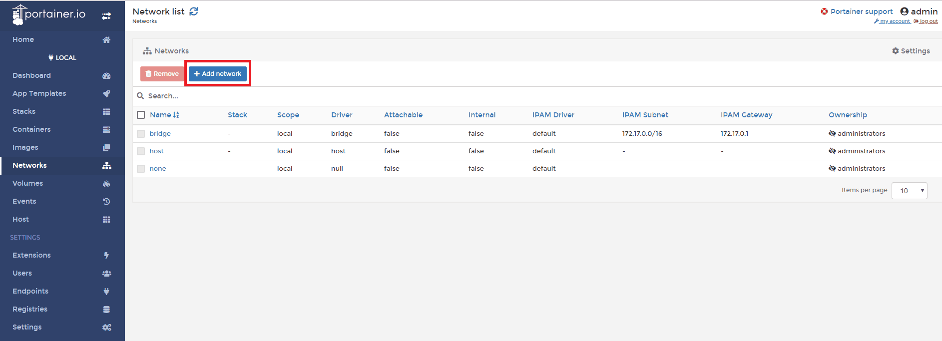
2. Create new Docker network
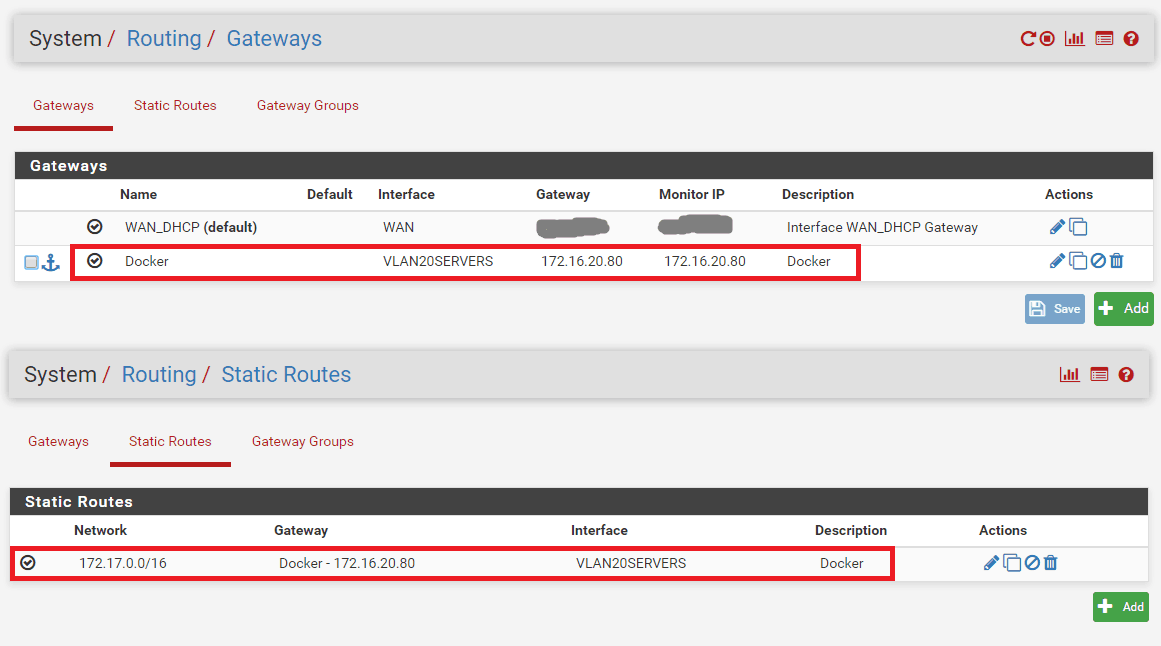
Use macvlan to create new network, but first check the subnet your docker host is on, we would like to create the same subnet on the docker network. This way, we can communicate directly to containers from our LAN network.
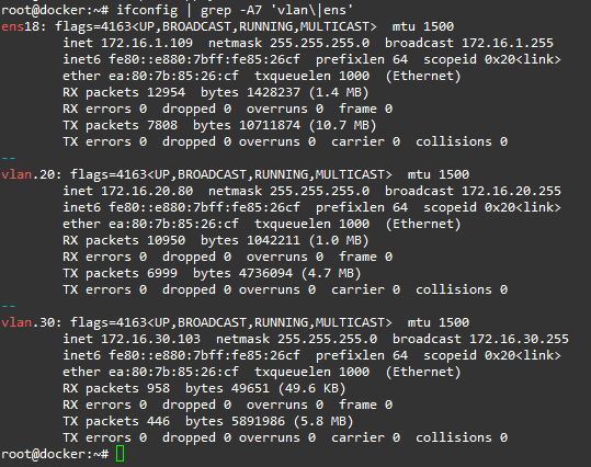
ifconfig or ip add

Find your network, ethX or ensX, in my case it’s ens18 with subnet 172.16.20.0/24

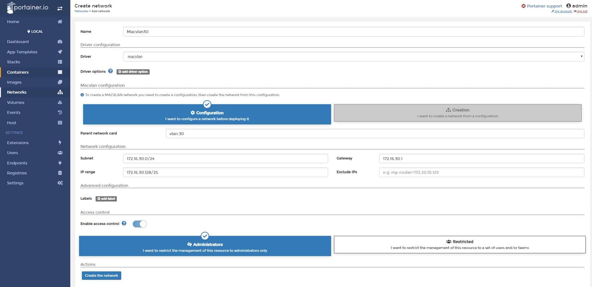
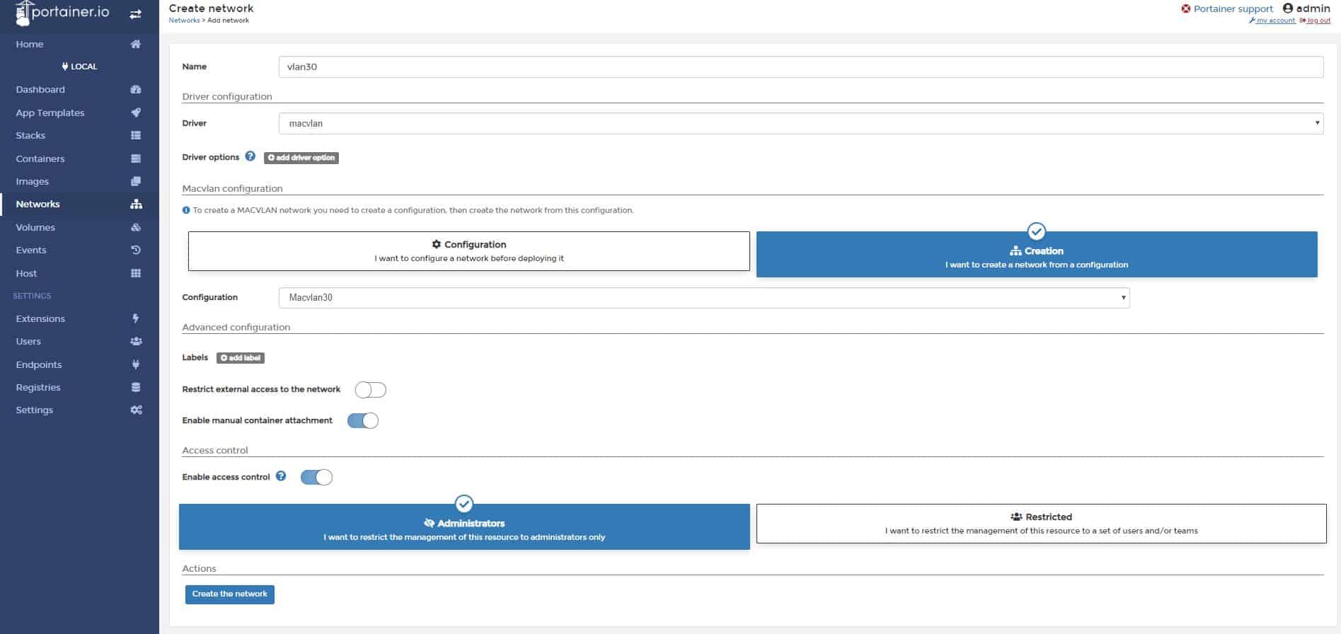
Now, create new network in the same subnet:

docker network create -d macvlan \
--subnet=172.16.20.0/24 \
--gateway=172.16.20.1 \
-o parent=ens18 localLAN

Command explanation:
-d macvlan = macvlan driver
–subnet = subnet of your local LAN
–gateway = your router IP
-o parent = network interface on the host with the same subnet
localLAN = name of the new Docker network, you can customize it

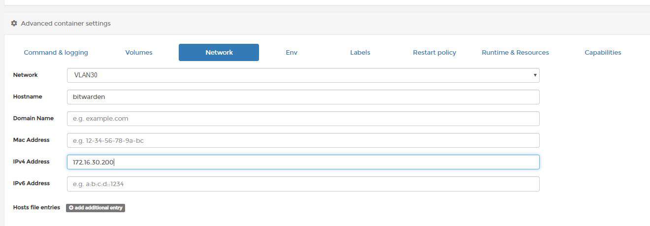
You can now run your container and have direct access to it from LAN.

docker run --net localLAN \
--ip=172.16.20.82 \
--name nginx_test -d nginx

Command explanation:
–net localLAN is the new Docker network we defined earlier
–ip=172.16.20.82, this is the IP you would like to assign to your container, make sure it doesn’t overlap with your LAN network IPs, make sure the IP is available
–name nginx_test, this is the name of your newly created container
-d nginx, detach nginx image (run in a background)

3. Nginx specific
We want to have Nginx configs and web content saved on our docker host, so we are going to mount local volumes to docker container.
First of all, we need to run the default nginx container and pull all the default config and web files to our local docker host.

docker run --net localLAN \
--ip=172.16.20.82 \
--name nginx_test -d nginx

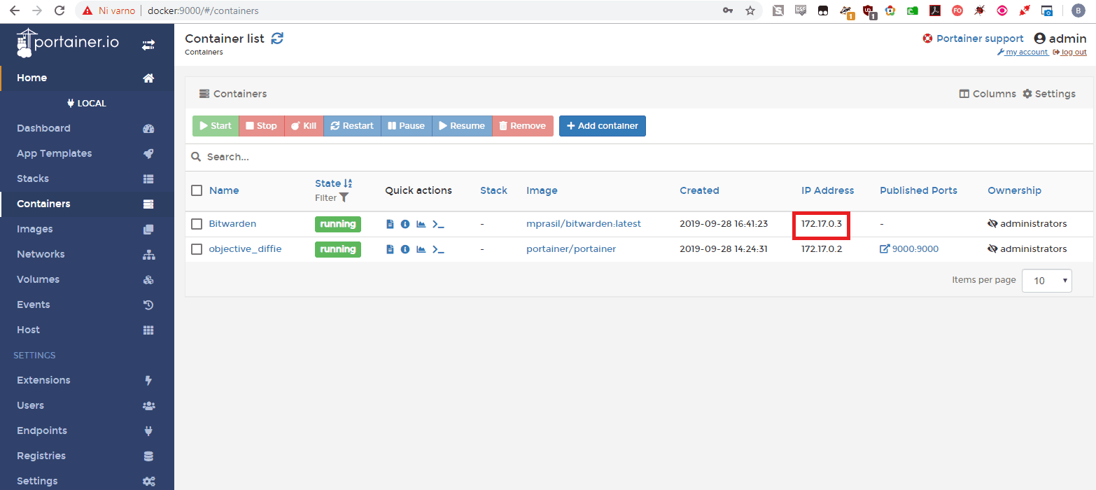
If you forget the IP of the container, you can check it with the following command:

docker inspect -f '{{range .NetworkSettings.Networks}}{{.IPAddress}}{{end}}' container_name

Create nginx folders on the docker host:

mkdir -p /etc/nginx /var/www

Copy default config files from container to the docker host:

docker cp nginx_test:/etc/nginx/ /etc/

Stop and delete the running container:

docker stop nginx_test
docker rm nginx_test

Star container with a mounted volumes:

docker run --net localLAN --ip=172.16.20.82 --name nginx_test \
-v /var/www:/usr/share/nginx/html \
-v /etc/nginx:/etc/nginx \
-d nginx

Go to /var/www on your docker host and create a file index.html with this contents:

<html>
<header><title>This is title</title></header>
<body>
Hello world
</body>
</html>

Your website should be displayed now at http://172.16.20.82.
You can change the content of the website live, without reloading container. Content folder is on the Docker host machine at /var/www/
If your container crashed for some reason, try running it in interactive mode, it should display the error:
First, check if container is running:

docker ps

If container is down, run it interactively to display errors:

docker start nginx_test -i

Or use docker logs:

docker logs nginx_test


I’m running Docker host VM on Proxmox and I want to put containers into different VLANs. There are 4 things you need to do:

1. Network port going to Proxmox hypervisor has to be trunk carrying VLANs (you need to setup this on your switch and router)
2. Network bridge in Proxmox has to be VLAN aware
3. Ubuntu guest VM (Docker host) needs VLAN interfaces to be configured
4. Add new network in Docker using VLAN

1. I will not cover how to setup trunk on your switch or router in this post.

2. VLAN aware bridge in Proxmox
Proxmox bridge has to be aware of VLAN trunk (tagged) traffic in order to pass it down to guest virtual machines.
Go to Datacenter -> proxmox -> Network -> vmbr0 -> Edit and tick VLAN Aware:

3. VM guest (Docker host) – Create VLAN interfaces
First off, in the Proxmox guest VM network device config, remove VLAN tag if you have one. That means all VLAN tagged traffic will go to guest VM.

Now login to your guest VM (Docker host) and add VLAN interfaces.

Ubuntu 18.x and later uses new type of network configuration using yaml files with netplan. Method for setting up vlans with previous version of Ubuntu is a little bit different, but the main principle is the same.

 nano /etc/netplan/50-cloud-init.yaml 
# This file is generated from information provided by
# the datasource. Changes to it will not persist across an instance.
# To disable cloud-init's network configuration capabilities, write a file
# /etc/cloud/cloud.cfg.d/99-disable-network-config.cfg with the following:
# network: {config: disabled}

network:
    ethernets:
        ens18:
            dhcp4: true
    version: 2
    vlans:
        vlan.20:
            id: 20
            link: ens18
            dhcp4: true
        vlan.30:
            id: 30
            link: ens18
            dhcp4: true

Replace ens18 with your parent network card. Add vlans accordingly. Since I map MAC addresses to IPs on my router I configured DHCP for VLAN interfaces. If you want to assign IP in the config, use directive “addresses: [172.16.0.2/24]” instead. Be aware, yaml files will not work with TABs, use spaces instead.

 netplan apply 

Your VLANs should be up and running:

4. Create new network for Docker

I’m using GUI for managing Docker called Portainer.

Go to Networks and click + Add network

Name: Macvlan30
Driver: macvlan
Parent network card: vlan.30
Subnet: 172.16.30.0/24
IP Range: 172.16.30.128/25
Gateway: 172.16.30.1

Click Create the network

Now we need to deploy the network. Click + Add network again.

Name: vlan30
Driver: macvlan
Macvlan configuration: select I want to create a network from a configuration
Configuration: Macvlan30
Enable manual container attachment: yes

Click Create the network.

Your new network is now ready for docker containers.

If you want assign a container to a network, go to Containers -> select container, go to the bottom and leave existing networks, then join a network vlan30.

Start the container, you should fall into vlan 30.

One caveat: DHCP request will get to your router, but you won’t get a response, because the host is not listening on the virtual MAC of the adapter so you’ll need to assign IP address of container manually or use experimental DHCP driver. You can also use Portainer GUI in container network options:

By default, Docker creates it’s own network on the host machine, thus you cannot access containers from external networks directly. For example, I would like to access Bitwarden container with IP 172.17.0.3 directly from my LAN network workstation (172.16.3.2).

Enable forwarding mode on the Docker host:

sysctl -w net.ipv4.ip_forward=1
iptables -A FORWARD -i docker0 -o ens18 -j ACCEPT
iptables -A FORWARD -i ens18 -o docker0 -j ACCEPT

In the commands above, replace “ens18” with your network card interface.

On your LAN router, create a gateway and a static route to 172.17.0.0/24 network. Your new gateway for this static route is IP of the machine hosting Docker (in my example 172.16.20.80). Different routers have different ways of setting up gateways and routes, read the manual.

LAN (172.16.3.0/24) –> Gateway – Docker host (172.16.20.80) –> Remote Network – Docker containers (172.17.0.0/24)

Edit: 172.17.0.0/16 should be 172.17.0.0/24 for my network

You can now access containers directly from LAN network.

Keep in mind Docker has it’s own mechanisms of achieving direct access to containers without fiddling with routes. One of the ways would be to assign container to a VLAN with macvlan driver: https://s55ma.radioamater.si/2019/09/29/proxmox-ubuntu-18-04-guest-vlan-trunk-for-docker-containers/.


After installing the docker-ce (https://docs.docker.com/install/linux/docker-ce/ubuntu/) and testing the setup, you’re greeted with the following error:

user@lxc-cont:~# sudo docker run hello-world

docker: Error response from daemon: OCI runtime create failed: container_linux.go:345: starting container process caused “process_linux.go:430: container init caused \”rootfs_linux.go:58: mounting \\\”proc\\\” to rootfs \\\”/var/lib/docker/vfs/dir/7334956ce039ef86a0d6b9e017c2166549cd4c4098ea51f29b98c39aeba4ac0b\\\” at \\\”/proc\\\” caused \\\”permission denied\\\”\””: unknown.
ERRO[0001] error waiting for container: context canceled

You need to allow the use of the keyctl() system call and nesting, be aware that this will expose procfs and sysfs contents of the host to the guest  and is a security concern (https://pve.proxmox.com/wiki/Linux_Container).

Login to your Proxmox host, via SSH or web shell.

Go to /etc/pve/local/ and edit your cointainer config file:

vi /etc/pve/local/lxc/<container_ID>.conf

Add  “features: keyctl=1,nesting=1” to the config file

Restart LXC container and you’re done, docker should run now.

There could be many reasons, in my case it was node_exporter added incorrectly to shellcmd, that caused PfSense to stuck at boot at configuring firewall in the console view.

The correct node_exporter syntax for shell cmd is:

bash -c "nohup node_exporter >/dev/null 2>&1 &"

What is shellcmd?

Shellcmd is a system utility used to manage commands on a system startup.
You can install it by going to System -> Package manager -> Available Packages -> Shellcmd
Access is at Services -> Shellcmd

Find node_exporter package at: http://pkg.freebsd.org/FreeBSD:11:amd64/latest/All/

At the time of writing this post: http://pkg.freebsd.org/FreeBSD:11:amd64/latest/All/node_exporter-0.18.1.txz

SSH to PfSense

pkg add http://pkg.freebsd.org/FreeBSD:11:amd64/latest/All/node_exporter-0.18.1.txz
rehash
service node_exporter onestart

EDIT:
How to start node_exporter in PfSense at boot:
https://s55ma.radioamater.si/2019/09/08/pfsense-stuck-at-boot-at-configuring-firewall/

What is node_exporter?
https://prometheus.io/docs/guides/node-exporter/


1. Login to the Proxmox webGUI, select desired node and click on disks. In my case, my new hard drive device is labeled as /dev/sdc.

2. Open Proxmox console and create disk partitions:

fdisk /dev/sdc

Create new partition: n
Select primary partition type: p
Leave the first and the last sectors default (press enter twice).
press w
Your new partition is now labeled the same as  the hard drive device with an added number 1 (/dev/sdc1).

3. Create physical volume:

pvcreate /dev/sdc1

4. Create volume group:

vgcreate Hitachi500G /dev/sdc1

You can name volume group whatever you want, I named mine Hitachi500G.

5. Go back to Proxmox webGUI
Select Datacenter -> Storage -> Add -> LVM

ID: custom name
Volume group: select the volume group you created in the step 4 and click Add.

Your new drive is now ready.

6. Create a shared directory on the proxmox host node (mount point)
Go to webGUI, click Datacenter -> Storage -> Add  Directory

ID: custom name
Directory: enter your mount point
Content: Disk image, Container
Click Add

You should now see your new directory mounted on the proxmox host. You can now share
this mount point with multiple LXC containers.

7. Select your LXC container and shut it down. While your LXC container is selected, go to Resources and click Add -> Mount point

Mount point ID: 0
Storage: Select storage you created in step 4
Disk size: You can define a custom size for any mount point
Path: This is the directory you created in step 6
Click Create

8. Start your container and check the new mount point.

References: https://www.hostfav.com/blog/index.php/2017/02/01/add-a-new-physical-hard-drive-to-proxmox-ve-4x-5x/

The problem:
apt-get dist-upgrade 
E: Failed to fetch https://enterprise.proxmox.com/debian/pve/dists/buster/InRelease 401 Unauthorized [IP: 66.70.154.81 443]
E: The repository ‘https://enterprise.proxmox.com/debian/pve buster InRelease’ is not signed.
N: Updating from such a repository can’t be done securely, and is therefore disabled by default.

Quick fix:
cd /etc/apt/sources.list.d/ 
cp pve-enterprise.list pve-no-subscription.list 
nano pve-enterprise.list

Comment out the first line and save:
#deb https://enterprise.proxmox.com/debian/pve buster pve-enterprise
nano pve-no-subscription.list

change deb https://enterprise.proxmox.com/debian/pve buster pve-enterprise
to deb http://download.proxmox.com/debian/pve buster pve-no-subscription

Upgrade should work now.

Reference: https://www.caretech.io/2018/06/08/how-to-update-proxmox-without-buying-a-subscription/

EDIT: Found a nicer way to do it: https://gist.github.com/whiskerz007/53c6aa5d624154bacbbc54880e1e3b2a
This script will not remove nagging popup with the newer versions of Proxmox, works up to 5.3.x version.

For a newer versions use this command:
 sed -i.bak "s/data.status !== 'Active'/false/g" /usr/share/javascript/proxmox-widget-toolkit/proxmoxlib.js && systemctl restart pveproxy.service

Make sure to clear your cookies and cache for this method to work.

PfSense supports only outbound traffic shapping so you can’t shape multiple LAN/VLAN interfaces without putting another PfSense box in front of it. The only way to shape it is to use only one physical interface LAN and tag other VLANS on that interface. You need to select only WAN and LAN interface for traffic shaping. All traffic that will pass from VLANs will go trough LAN interface where QOS traffic shaper will catch it. If you don’t do it via only one interface, traffic shaping will work, but the VLAN to VLAN traffic will be limited to the speed of a WAN download bandwidth.

For start, you can use traffic shaping wizard and modify rules after.

Go to:

Firewall -> Traffic Shaper -> Wizards -> Multiple LAN/WAN

Select one WAN connection and one LAN connection:

For interface select LAN and WAN, scheduler should be HFSC (you can choose another one if you like, but this post is about HFSC setup).

Define your WAN upload and download speed and continue wizzard till the end and save.

Go to:

Firewall -> Traffic shaper

Click on LAN and set bandwidth to your physical interface speed.

Set qLink bandwidth percentage to: ((LAN bandwidth – WAN download bandwidth) / 10)

Example:

My LAN bandwidth = 1000 Mbit

My WAN download banwidth = 200 Mbit

(1000 – 200) / 10 = 80%

The sum of parent trees has to be 100%

Save.

All you have to do now is add two more floating rules. Rules added by the wizzard are good enough to get an idea how it works. You can later add custom ports, depends on what you need.

Go to:

Firewall -> Rules -> Floating

We will add a rule to catch all traffic that does not fall under defined floating rules created by the wizzard. We will put all not defined traffic to qOtherLow queue. The important thing is to have rules added at the top of the floating rules and not at the bottom.


Add rule 1:

Match, interface: WAN, direction: any, protocol: TCP, source: any, destination: any, destination port range: from any to any

Advanced options: Ackqueue / Queue: qACK / qOtherLow


Add rule 2: 

Match, interface: WAN, direction: any, protocol: UDP, source: any, destination: any, destination port range: from any to any

Advanced options: Ackqueue / Queue: none / qOtherLow

The two created rules have to be at the top:

Basic traffic shaping should work now. It’s up to you know to fine tune the rules. Check the status of traffic shaper at Status -> Queues

qLink queue is VLAN <-> VLAN traffic while all the queues bellow +/-qInternet are VLAN <-> WAN traffic

Downsides of this setup:

  • You are limited to only one physical interface for VLAN traffic meaning your VLAN to VLAN bandwidth can suffer with multiple heavy users on a local network (like transferring a lot of files from local servers to local clients). You could probably solve that with LAN bridges but I don’t know how a QOS would behave in that case.
  • You can’t run squid proxy service because download traffic on port 80 and 443 will bypass traffic shaper (it can probably be done with some tweaking but I haven’t tested it yet).

This is useful when you can’t use peer to peer (site to site) tunnel. For example, when you don’t have administrative access to a remote network (you can’t open ports, you can only go out – egress). To bypass this and gain access to remote network devices, you can simply install a VPN client on the remote network and make it act as a gateway for your local network. I will not go trough basic OpenVPN server configuration (generating certs, adding users etc), I will only pinpoint the parts that differ from a normal VPN client server setup.

Example:

Remote network: 192.168.10.0/24 (Client side)

Local network: 192.168.1.0/24 (Server side)

1. Go to OpenVPN server settings, under advanced configuration, custom options and enter:

 push "route 192.168.1.0 255.255.255.0";

route 192.168.10.0 255.255.255.0; 

2. Go to OpenVPN client specific overrides tab and add a new rule. Select your OpenVPN server, enter common name (name of the user – VPN client), under IPv4 remote network/s enter: 192.168.10.0/24

3. If you haven’t already, you have to assign an interface to your VPN server. Go to Interfaces, Assignments, Available network ports: ovpns1, click Add and save. Click on your newly created interface, check box Enable interface and add a description: OpenVPN1 (name it however you want), save.

4. Go to System, routing, static routes.

Add a new route, destination network: 192.168.10.0/24

Gateway: OpenVPN1

5. You need to enable NAT and forwarding on a client, this example is for a linux client:

 sysctl -w net.ipv4.ip_forward=1

iptables -t nat -A POSTROUTING -o eth0 -j MASQUERADE

iptables -t nat -A POSTROUTING -o tun0 -j MASQUERADE 

6. Connect your VPN client, you should be able to access devices behind the client from your local network.

To connect via RTSP:

rtsp://camera_username:camera_password@IP:rtsp_port/live/ch00_1

Example:

rtsp://admin:admin123@192.168.30.102:554/live/ch00_1

If you are filtering outgoing connections, allow this outgoing ports to camera:

554 TCP

6970-6990 UDP

You can test RTSP stream with VLC media player.

Possible bug: When you connect to the camera with your phone, disconnect from it and then try to open rtsp stream in VLC media player, it will only load the first frame and stuck there. You need to reboot the camera, connect to rtsp with VLC media player without accessing it via mobile device.

Extra note: It’s advisable to block outgoing traffic from camera into internet. My camera is connecting to some IP with weird ports.

Quick whois showed me this IP belongs to alibaba.com. I did not sniff the traffic, so I’m not sure if the nature of it is spyware. It’s probably their cloud service or some other service.

For the extra paranoid, physically disconnect the microphone on the camera:

TL;DR:

Xerox phaser 3020 black ink percentage remaining – SNMP cacti data and graph template at the bottom of this post.


With some tweaks this method should also works for other brand printers.

With the help of this article: https://thwack.solarwinds.com/docs/DOC-171511 I could set up a cacti template for my Xerox 3020 printer. Some printers return ink level value in percents but in my case I got only the raw value.

1. Get SNMP toner max capacity value, OID for that is 1.3.6.1.2.1.43.11.1.1.8.1.1

root@cacti: snmpget -v2c -c public 192.168.0.251 1.3.6.1.2.1.43.11.1.1.8.1.1
SNMPv2-SMI::mib-2.43.11.1.1.8.1.1 = INTEGER: 700

700 is the raw value for 100% toner capacity.

2. Get SNMP toner current levels value, OID for that is 1.3.6.1.2.1.43.11.1.1.9.1.1

root@cacti: snmpget -v2c -c public 192.168.0.251 1.3.6.1.2.1.43.11.1.1.9.1.1
SNMPv2-SMI::mib-2.43.11.1.1.9.1.1 = INTEGER: 686

686 is the current raw value of my toner levels. To calculate toner ink percentage remaining we need to divide current raw value (686) with max raw value (700) and multiply it by 100. 686 / 700 * 100 = 98 (percentage of ink remaining). Since the max raw value is a nice number (700), we can just divide current raw value with 7, 686/7 = 98. We can use this formula for our CDEF definitions in cacti later. Remember, this is only for Xerox 3020, other brand printers can output different raw values and you need to correct this formula accordingly.

Xerox 3020 ink remaining percentage formula: raw_current_ink_level / 7

3. Login to cacti and go to Console -> Presets -> CDEFs

Click plus sign and create new CDEF and name it Xerox toner percentage

Click plus at CDEF Items.

CDEF Item Type: Special Data Source

CDEF Item Value: Current Graph Item Data Source

Click Save

Click plus at CDEF Items.

CDEF Item Type: Custom String

CDEF Item Value: 7 (this is the value cacti will use to divide raw data)

Click Save

Click plus at CDEF Items.

CDEF Item Type: Operator

CDEF Item Value: / (this will tell cacti to use a divide operation with the custom string we defined in a previous step).

Click Save

4. Go to Console -> Templates -> Data Source

Click plus to create new data source template and name it Printer – black toner current

Name: |host_description| – black toner current

Data Input Method: Get SNMP Data

Data Source Active: tick the right box

Internal Data Source Name: toner_current

Click Create

New Custom Data field will appear.

OID: 1.3.6.1.2.1.43.11.1.1.9.1.1

Click Save

5.1 Go to Console -> Templates -> Graph

Click plus sign

Name: Printer – black toner levels

Title: Printer – black toner levels

Vertical Label: percent

Tick Rigid Boundaries Mode

Upper Limit: 100

Click Create

5.2 Now click plus sign at Graph Template Items

Graph Item Type: AREA

Data Source: Printer – black toner current

Color: select what you like

Consolidation Function: AVERAGE

CDEF Function: Xerox toner percentage

Text Format: Available

Click save

Add another Graph template item

Graph Item Type: GPRINT

Data Source: Printer – black toner current

Consolidation Function: LAST

CDEF Function: Xerox toner percentage

GPRINT Type: Percent(Round down to the nearest decimal)

Text format: Current:

Click Save

Add another Graph template item

Graph Item Type: LINE1

Data Source: Printer – black toner current

Consolidation function: AVERAGE

CDEF function: Xeror toner percentage

Save

Your graph is now ready to device assignment.

Final result:

Download data and graph templates for xerox phaser 3020:

xerox_3020_cacti_toner_level_template