1. Pull the Nginx image first

 docker pull nginx 

2. Create new Docker network
Use macvlan to create new network, but first check the subnet your docker host is on, we would like to create the same subnet on the docker network. This way, we can communicate directly to containers from our LAN network.

ifconfig or ip add

Find your network, ethX or ensX, in my case it’s ens18 with subnet 172.16.20.0/24

Now, create new network in the same subnet:

docker network create -d macvlan \
--subnet=172.16.20.0/24 \
--gateway=172.16.20.1 \
-o parent=ens18 localLAN

Command explanation:
-d macvlan = macvlan driver
–subnet = subnet of your local LAN
–gateway = your router IP
-o parent = network interface on the host with the same subnet
localLAN = name of the new Docker network, you can customize it

You can now run your container and have direct access to it from LAN.

docker run --net localLAN \
--ip=172.16.20.82 \
--name nginx_test -d nginx

Command explanation:
–net localLAN is the new Docker network we defined earlier
–ip=172.16.20.82, this is the IP you would like to assign to your container, make sure it doesn’t overlap with your LAN network IPs, make sure the IP is available
–name nginx_test, this is the name of your newly created container
-d nginx, detach nginx image (run in a background)

3. Nginx specific
We want to have Nginx configs and web content saved on our docker host, so we are going to mount local volumes to docker container.
First of all, we need to run the default nginx container and pull all the default config and web files to our local docker host.

docker run --net localLAN \
--ip=172.16.20.82 \
--name nginx_test -d nginx

If you forget the IP of the container, you can check it with the following command:

docker inspect -f '{{range .NetworkSettings.Networks}}{{.IPAddress}}{{end}}' container_name

Create nginx folders on the docker host:

mkdir -p /etc/nginx /var/www

Copy default config files from container to the docker host:

docker cp nginx_test:/etc/nginx/ /etc/

Stop and delete the running container:

docker stop nginx_test
docker rm nginx_test

Star container with a mounted volumes:

docker run --net localLAN --ip=172.16.20.82 --name nginx_test \
-v /var/www:/usr/share/nginx/html \
-v /etc/nginx:/etc/nginx \
-d nginx

Go to /var/www on your docker host and create a file index.html with this contents:

<html>
<header><title>This is title</title></header>
<body>
Hello world
</body>
</html>

Your website should be displayed now at http://172.16.20.82.
You can change the content of the website live, without reloading container. Content folder is on the Docker host machine at /var/www/
If your container crashed for some reason, try running it in interactive mode, it should display the error:
First, check if container is running:

docker ps

If container is down, run it interactively to display errors:

docker start nginx_test -i

Or use docker logs:

docker logs nginx_test


I’m running Docker host VM on Proxmox and I want to put containers into different VLANs. There are 4 things you need to do:

1. Network port going to Proxmox hypervisor has to be trunk carrying VLANs (you need to setup this on your switch and router)
2. Network bridge in Proxmox has to be VLAN aware
3. Ubuntu guest VM (Docker host) needs VLAN interfaces to be configured
4. Add new network in Docker using VLAN

1. I will not cover how to setup trunk on your switch or router in this post.

2. VLAN aware bridge in Proxmox
Proxmox bridge has to be aware of VLAN trunk (tagged) traffic in order to pass it down to guest virtual machines.
Go to Datacenter -> proxmox -> Network -> vmbr0 -> Edit and tick VLAN Aware:

3. VM guest (Docker host) – Create VLAN interfaces
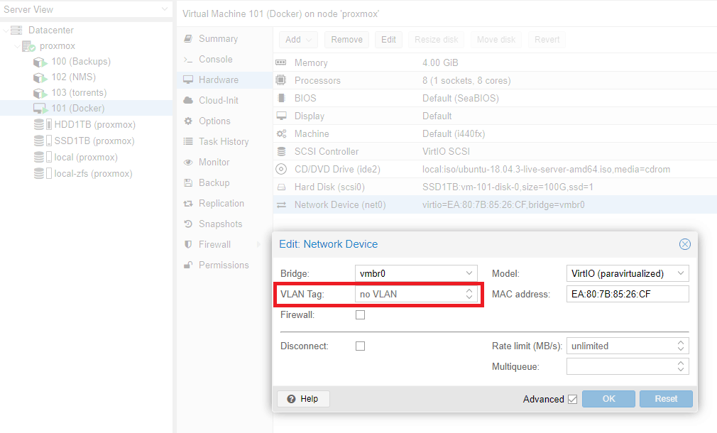
First off, in the Proxmox guest VM network device config, remove VLAN tag if you have one. That means all VLAN tagged traffic will go to guest VM.

Now login to your guest VM (Docker host) and add VLAN interfaces.

Ubuntu 18.x and later uses new type of network configuration using yaml files with netplan. Method for setting up vlans with previous version of Ubuntu is a little bit different, but the main principle is the same.

 nano /etc/netplan/50-cloud-init.yaml 
# This file is generated from information provided by
# the datasource. Changes to it will not persist across an instance.
# To disable cloud-init's network configuration capabilities, write a file
# /etc/cloud/cloud.cfg.d/99-disable-network-config.cfg with the following:
# network: {config: disabled}

network:
    ethernets:
        ens18:
            dhcp4: true
    version: 2
    vlans:
        vlan.20:
            id: 20
            link: ens18
            dhcp4: true
        vlan.30:
            id: 30
            link: ens18
            dhcp4: true

Replace ens18 with your parent network card. Add vlans accordingly. Since I map MAC addresses to IPs on my router I configured DHCP for VLAN interfaces. If you want to assign IP in the config, use directive “addresses: [172.16.0.2/24]” instead. Be aware, yaml files will not work with TABs, use spaces instead.

 netplan apply 

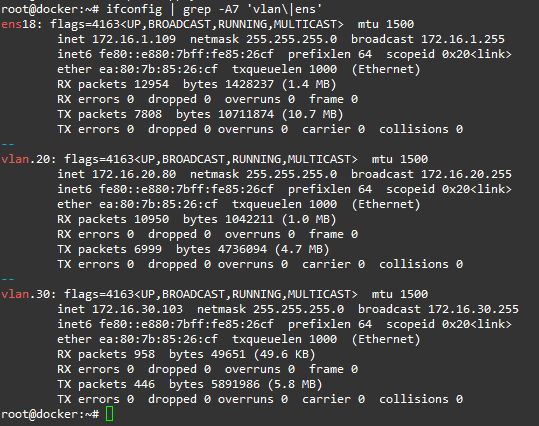
Your VLANs should be up and running:

4. Create new network for Docker

I’m using GUI for managing Docker called Portainer.

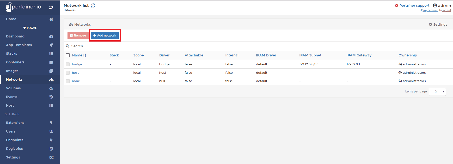
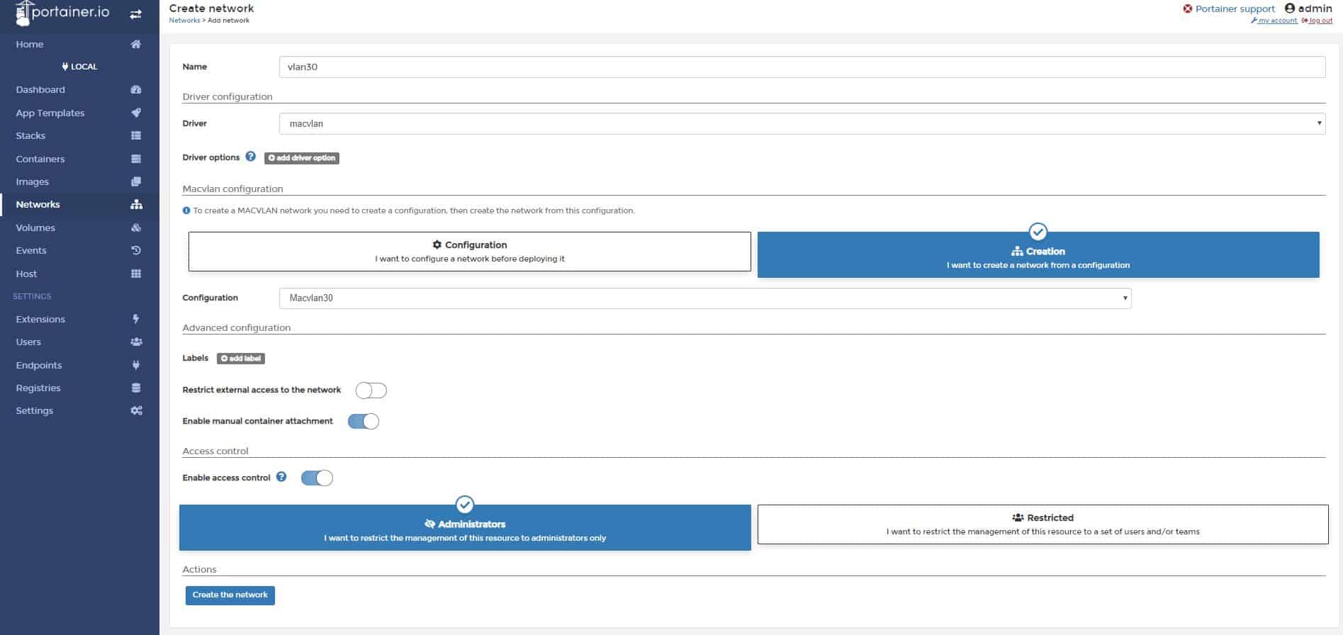
Go to Networks and click + Add network

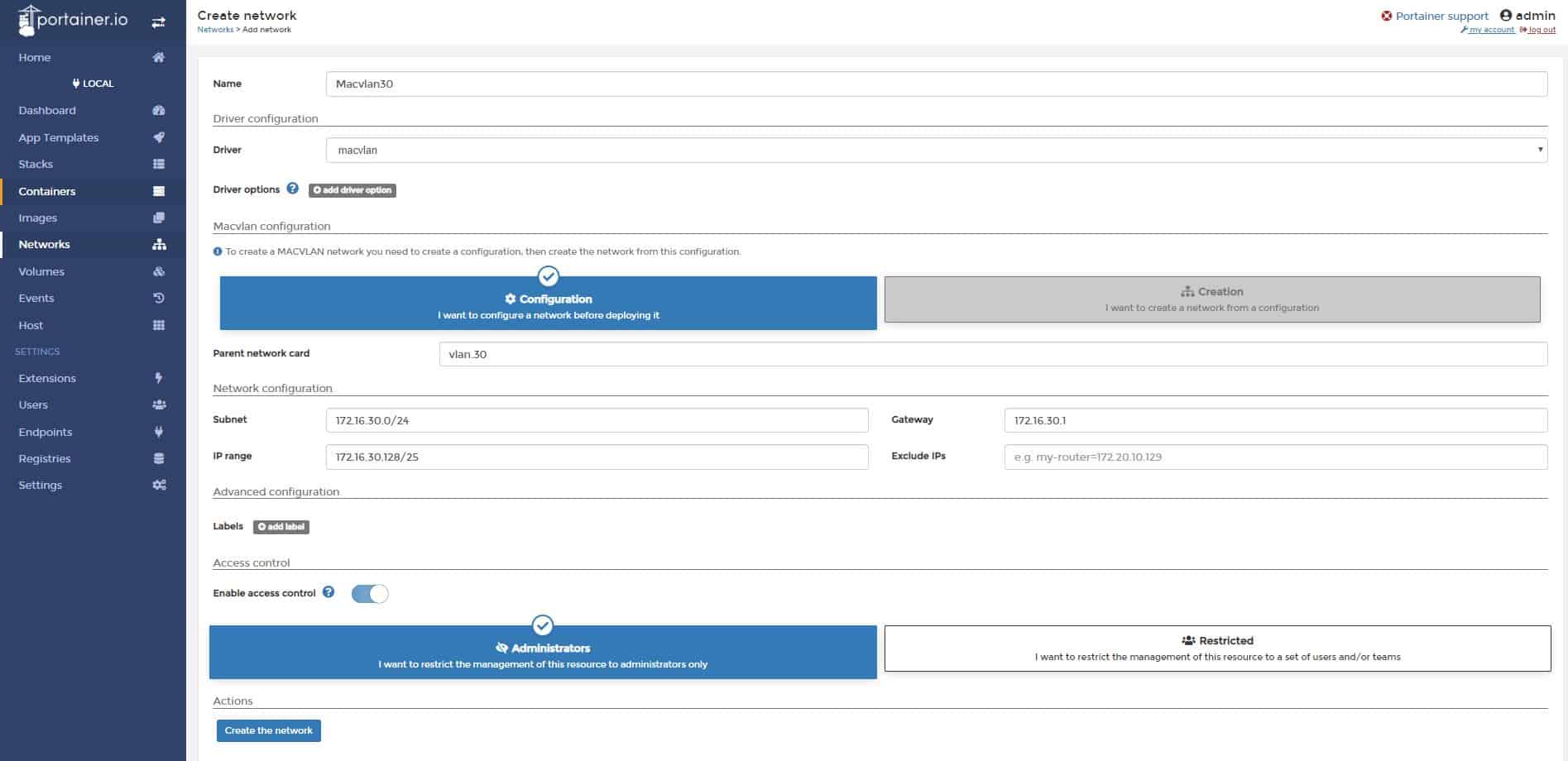
Name: Macvlan30
Driver: macvlan
Parent network card: vlan.30
Subnet: 172.16.30.0/24
IP Range: 172.16.30.128/25
Gateway: 172.16.30.1

Click Create the network

Now we need to deploy the network. Click + Add network again.

Name: vlan30
Driver: macvlan
Macvlan configuration: select I want to create a network from a configuration
Configuration: Macvlan30
Enable manual container attachment: yes

Click Create the network.

Your new network is now ready for docker containers.

If you want assign a container to a network, go to Containers -> select container, go to the bottom and leave existing networks, then join a network vlan30.

Start the container, you should fall into vlan 30.

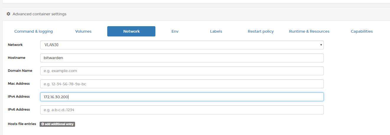
One caveat: DHCP request will get to your router, but you won’t get a response, because the host is not listening on the virtual MAC of the adapter so you’ll need to assign IP address of container manually or use experimental DHCP driver. You can also use Portainer GUI in container network options:

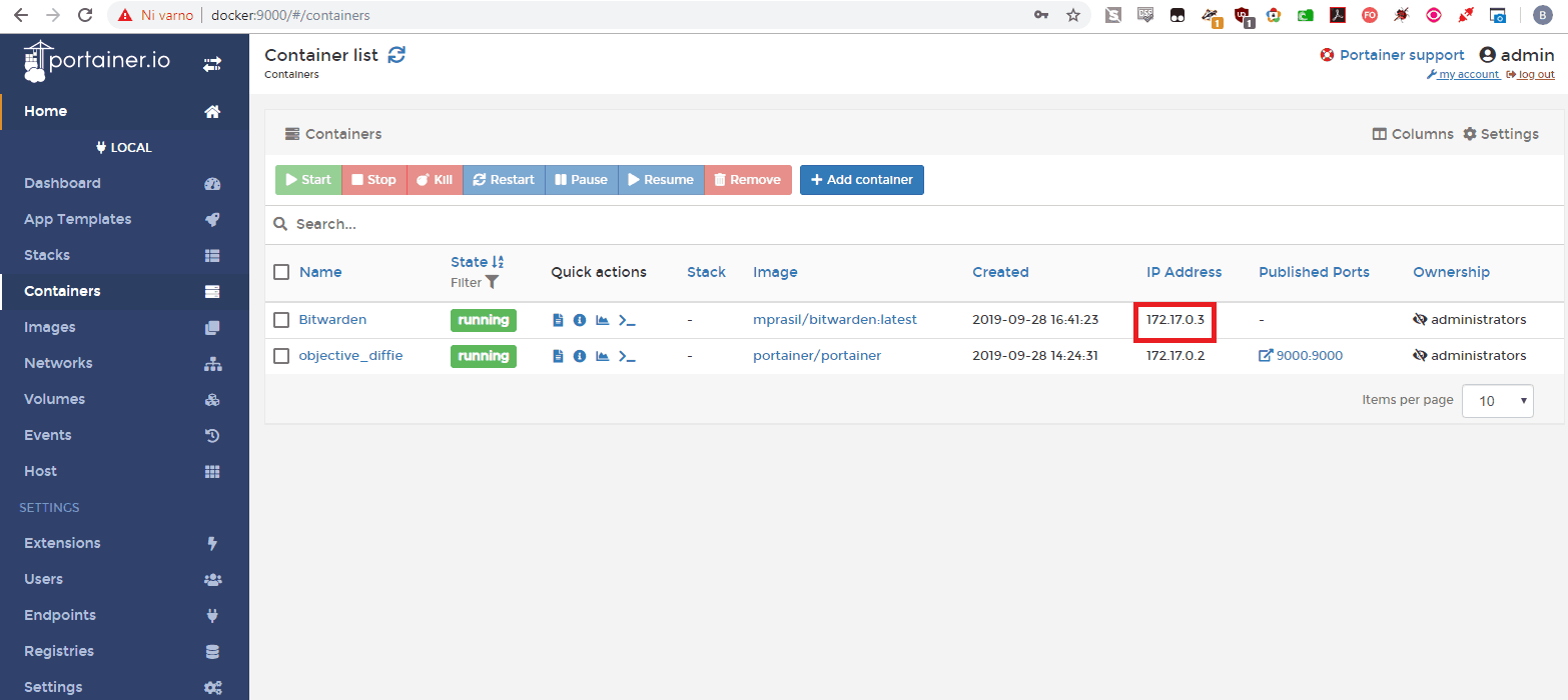
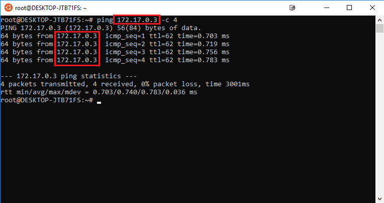
By default, Docker creates it’s own network on the host machine, thus you cannot access containers from external networks directly. For example, I would like to access Bitwarden container with IP 172.17.0.3 directly from my LAN network workstation (172.16.3.2).

Enable forwarding mode on the Docker host:

sysctl -w net.ipv4.ip_forward=1
iptables -A FORWARD -i docker0 -o ens18 -j ACCEPT
iptables -A FORWARD -i ens18 -o docker0 -j ACCEPT

In the commands above, replace “ens18” with your network card interface.

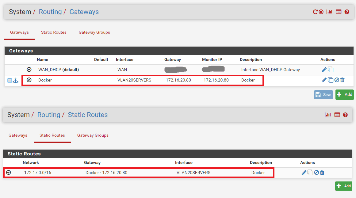
On your LAN router, create a gateway and a static route to 172.17.0.0/24 network. Your new gateway for this static route is IP of the machine hosting Docker (in my example 172.16.20.80). Different routers have different ways of setting up gateways and routes, read the manual.

LAN (172.16.3.0/24) –> Gateway – Docker host (172.16.20.80) –> Remote Network – Docker containers (172.17.0.0/24)

Edit: 172.17.0.0/16 should be 172.17.0.0/24 for my network

You can now access containers directly from LAN network.

Keep in mind Docker has it’s own mechanisms of achieving direct access to containers without fiddling with routes. One of the ways would be to assign container to a VLAN with macvlan driver: https://s55ma.radioamater.si/2019/09/29/proxmox-ubuntu-18-04-guest-vlan-trunk-for-docker-containers/.


After installing the docker-ce (https://docs.docker.com/install/linux/docker-ce/ubuntu/) and testing the setup, you’re greeted with the following error:

user@lxc-cont:~# sudo docker run hello-world

docker: Error response from daemon: OCI runtime create failed: container_linux.go:345: starting container process caused “process_linux.go:430: container init caused \”rootfs_linux.go:58: mounting \\\”proc\\\” to rootfs \\\”/var/lib/docker/vfs/dir/7334956ce039ef86a0d6b9e017c2166549cd4c4098ea51f29b98c39aeba4ac0b\\\” at \\\”/proc\\\” caused \\\”permission denied\\\”\””: unknown.
ERRO[0001] error waiting for container: context canceled

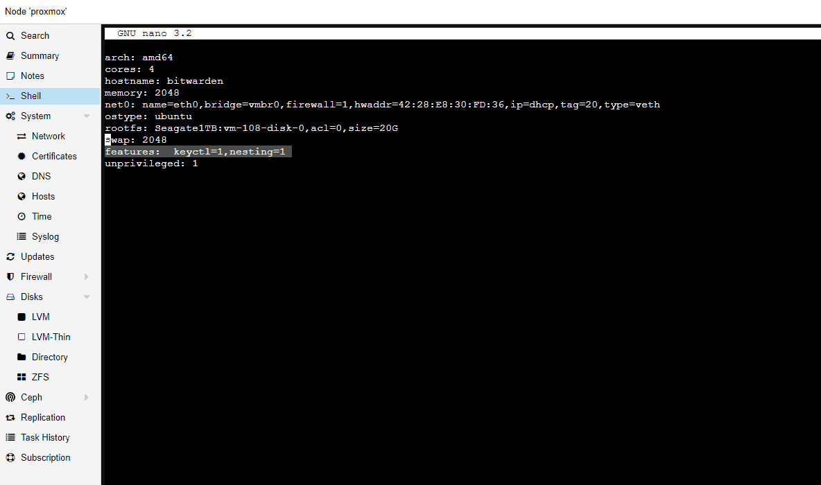
You need to allow the use of the keyctl() system call and nesting, be aware that this will expose procfs and sysfs contents of the host to the guest  and is a security concern (https://pve.proxmox.com/wiki/Linux_Container).

Login to your Proxmox host, via SSH or web shell.

Go to /etc/pve/local/ and edit your cointainer config file:

vi /etc/pve/local/lxc/<container_ID>.conf

Add  “features: keyctl=1,nesting=1” to the config file

Restart LXC container and you’re done, docker should run now.

There could be many reasons, in my case it was node_exporter added incorrectly to shellcmd, that caused PfSense to stuck at boot at configuring firewall in the console view.

The correct node_exporter syntax for shell cmd is:

bash -c "nohup node_exporter >/dev/null 2>&1 &"

What is shellcmd?

Shellcmd is a system utility used to manage commands on a system startup.
You can install it by going to System -> Package manager -> Available Packages -> Shellcmd
Access is at Services -> Shellcmd

Find node_exporter package at: http://pkg.freebsd.org/FreeBSD:11:amd64/latest/All/

At the time of writing this post: http://pkg.freebsd.org/FreeBSD:11:amd64/latest/All/node_exporter-0.18.1.txz

SSH to PfSense

pkg add http://pkg.freebsd.org/FreeBSD:11:amd64/latest/All/node_exporter-0.18.1.txz
rehash
service node_exporter onestart

EDIT:
How to start node_exporter in PfSense at boot:
https://s55ma.radioamater.si/2019/09/08/pfsense-stuck-at-boot-at-configuring-firewall/

What is node_exporter?
https://prometheus.io/docs/guides/node-exporter/


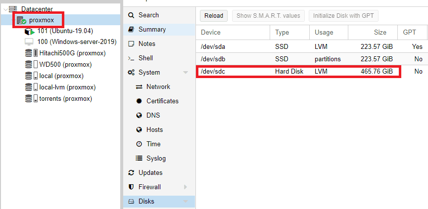
1. Login to the Proxmox webGUI, select desired node and click on disks. In my case, my new hard drive device is labeled as /dev/sdc.

2. Open Proxmox console and create disk partitions:

fdisk /dev/sdc

Create new partition: n
Select primary partition type: p
Leave the first and the last sectors default (press enter twice).
press w
Your new partition is now labeled the same as  the hard drive device with an added number 1 (/dev/sdc1).

3. Create physical volume:

pvcreate /dev/sdc1

4. Create volume group:

vgcreate Hitachi500G /dev/sdc1

You can name volume group whatever you want, I named mine Hitachi500G.

5. Go back to Proxmox webGUI
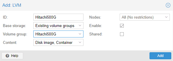
Select Datacenter -> Storage -> Add -> LVM

ID: custom name
Volume group: select the volume group you created in the step 4 and click Add.

Your new drive is now ready.

6. Create a shared directory on the proxmox host node (mount point)
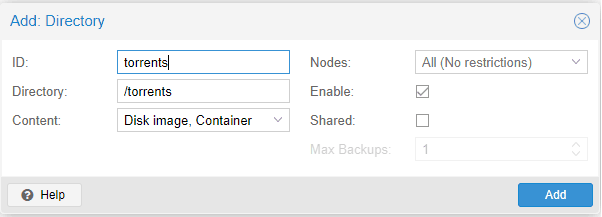
Go to webGUI, click Datacenter -> Storage -> Add  Directory

ID: custom name
Directory: enter your mount point
Content: Disk image, Container
Click Add

You should now see your new directory mounted on the proxmox host. You can now share
this mount point with multiple LXC containers.

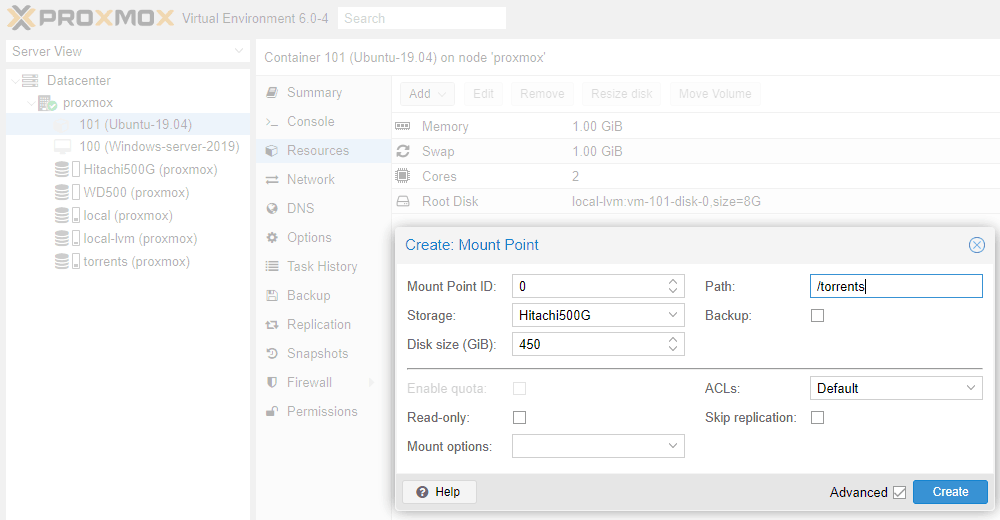
7. Select your LXC container and shut it down. While your LXC container is selected, go to Resources and click Add -> Mount point

Mount point ID: 0
Storage: Select storage you created in step 4
Disk size: You can define a custom size for any mount point
Path: This is the directory you created in step 6
Click Create

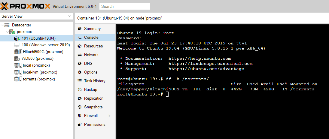
8. Start your container and check the new mount point.

References: https://www.hostfav.com/blog/index.php/2017/02/01/add-a-new-physical-hard-drive-to-proxmox-ve-4x-5x/

The problem:
apt-get dist-upgrade 
E: Failed to fetch https://enterprise.proxmox.com/debian/pve/dists/buster/InRelease 401 Unauthorized [IP: 66.70.154.81 443]
E: The repository ‘https://enterprise.proxmox.com/debian/pve buster InRelease’ is not signed.
N: Updating from such a repository can’t be done securely, and is therefore disabled by default.

Quick fix:
cd /etc/apt/sources.list.d/ 
cp pve-enterprise.list pve-no-subscription.list 
nano pve-enterprise.list

Comment out the first line and save:
#deb https://enterprise.proxmox.com/debian/pve buster pve-enterprise
nano pve-no-subscription.list

change deb https://enterprise.proxmox.com/debian/pve buster pve-enterprise
to deb http://download.proxmox.com/debian/pve buster pve-no-subscription

Upgrade should work now.

Reference: https://www.caretech.io/2018/06/08/how-to-update-proxmox-without-buying-a-subscription/

EDIT: Found a nicer way to do it: https://gist.github.com/whiskerz007/53c6aa5d624154bacbbc54880e1e3b2a
This script will not remove nagging popup with the newer versions of Proxmox, works up to 5.3.x version.

For a newer versions use this command:
 sed -i.bak "s/data.status !== 'Active'/false/g" /usr/share/javascript/proxmox-widget-toolkit/proxmoxlib.js && systemctl restart pveproxy.service

Make sure to clear your cookies and cache for this method to work.

PfSense supports only outbound traffic shapping so you can’t shape multiple LAN/VLAN interfaces without putting another PfSense box in front of it. The only way to shape it is to use only one physical interface LAN and tag other VLANS on that interface. You need to select only WAN and LAN interface for traffic shaping. All traffic that will pass from VLANs will go trough LAN interface where QOS traffic shaper will catch it. If you don’t do it via only one interface, traffic shaping will work, but the VLAN to VLAN traffic will be limited to the speed of a WAN download bandwidth.

For start, you can use traffic shaping wizard and modify rules after.

Go to:

Firewall -> Traffic Shaper -> Wizards -> Multiple LAN/WAN

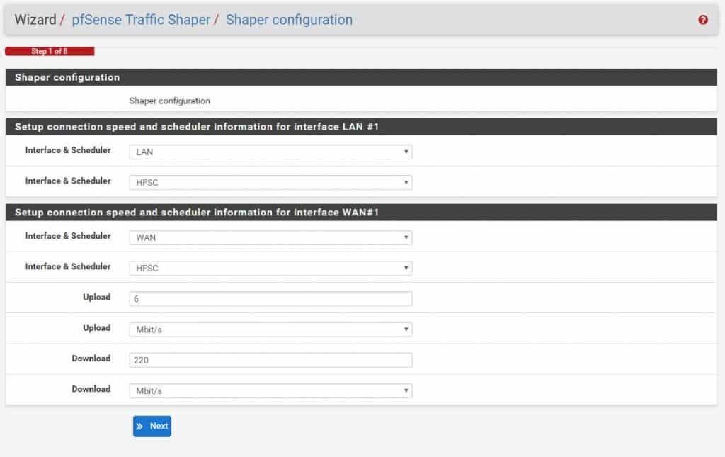
Select one WAN connection and one LAN connection:

For interface select LAN and WAN, scheduler should be HFSC (you can choose another one if you like, but this post is about HFSC setup).

Define your WAN upload and download speed and continue wizzard till the end and save.

Go to:

Firewall -> Traffic shaper

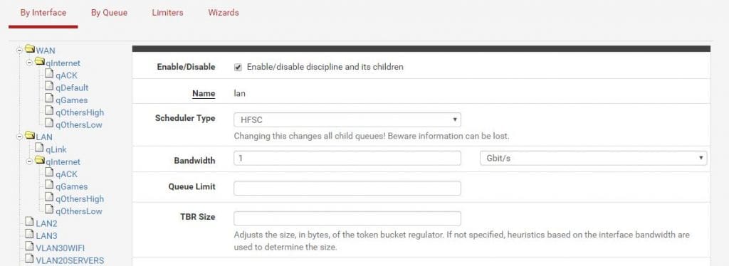
Click on LAN and set bandwidth to your physical interface speed.

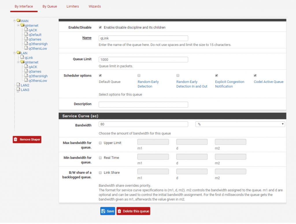
Set qLink bandwidth percentage to: ((LAN bandwidth – WAN download bandwidth) / 10)

Example:

My LAN bandwidth = 1000 Mbit

My WAN download banwidth = 200 Mbit

(1000 – 200) / 10 = 80%

The sum of parent trees has to be 100%

Save.

All you have to do now is add two more floating rules. Rules added by the wizzard are good enough to get an idea how it works. You can later add custom ports, depends on what you need.

Go to:

Firewall -> Rules -> Floating

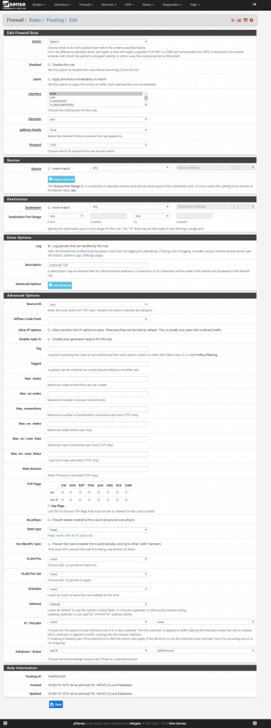
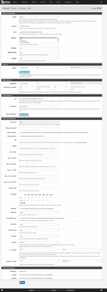
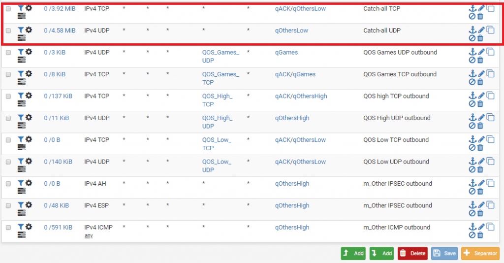
We will add a rule to catch all traffic that does not fall under defined floating rules created by the wizzard. We will put all not defined traffic to qOtherLow queue. The important thing is to have rules added at the top of the floating rules and not at the bottom.


Add rule 1:

Match, interface: WAN, direction: any, protocol: TCP, source: any, destination: any, destination port range: from any to any

Advanced options: Ackqueue / Queue: qACK / qOtherLow


Add rule 2: 

Match, interface: WAN, direction: any, protocol: UDP, source: any, destination: any, destination port range: from any to any

Advanced options: Ackqueue / Queue: none / qOtherLow

The two created rules have to be at the top:

Basic traffic shaping should work now. It’s up to you know to fine tune the rules. Check the status of traffic shaper at Status -> Queues

qLink queue is VLAN <-> VLAN traffic while all the queues bellow +/-qInternet are VLAN <-> WAN traffic

Downsides of this setup:

  • You are limited to only one physical interface for VLAN traffic meaning your VLAN to VLAN bandwidth can suffer with multiple heavy users on a local network (like transferring a lot of files from local servers to local clients). You could probably solve that with LAN bridges but I don’t know how a QOS would behave in that case.
  • You can’t run squid proxy service because download traffic on port 80 and 443 will bypass traffic shaper (it can probably be done with some tweaking but I haven’t tested it yet).

This is useful when you can’t use peer to peer (site to site) tunnel. For example, when you don’t have administrative access to a remote network (you can’t open ports, you can only go out – egress). To bypass this and gain access to remote network devices, you can simply install a VPN client on the remote network and make it act as a gateway for your local network. I will not go trough basic OpenVPN server configuration (generating certs, adding users etc), I will only pinpoint the parts that differ from a normal VPN client server setup.

Example:

Remote network: 192.168.10.0/24 (Client side)

Local network: 192.168.1.0/24 (Server side)

1. Go to OpenVPN server settings, under advanced configuration, custom options and enter:

 push "route 192.168.1.0 255.255.255.0";

route 192.168.10.0 255.255.255.0; 

2. Go to OpenVPN client specific overrides tab and add a new rule. Select your OpenVPN server, enter common name (name of the user – VPN client), under IPv4 remote network/s enter: 192.168.10.0/24

3. If you haven’t already, you have to assign an interface to your VPN server. Go to Interfaces, Assignments, Available network ports: ovpns1, click Add and save. Click on your newly created interface, check box Enable interface and add a description: OpenVPN1 (name it however you want), save.

4. Go to System, routing, static routes.

Add a new route, destination network: 192.168.10.0/24

Gateway: OpenVPN1

5. You need to enable NAT and forwarding on a client, this example is for a linux client:

 sysctl -w net.ipv4.ip_forward=1

iptables -t nat -A POSTROUTING -o eth0 -j MASQUERADE

iptables -t nat -A POSTROUTING -o tun0 -j MASQUERADE 

6. Connect your VPN client, you should be able to access devices behind the client from your local network.

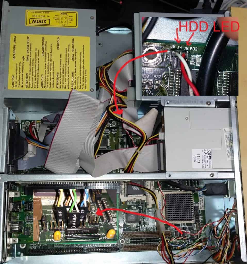
I couldn’t find any manuals or schematics online about this exact board so I had to figure out where to plug the HDD LED activity light on the board. It’ should be written on the motherboard like the other front panel items (power led, turbo led, turbo switch, reset) but that wasn’t the case. HDD IDE LED pins are located at the top of the motherboard (J6 and J4 pins).

Model number of the board:

To connect via RTSP:

rtsp://camera_username:camera_password@IP:rtsp_port/live/ch00_1

Example:

rtsp://admin:admin123@192.168.30.102:554/live/ch00_1

If you are filtering outgoing connections, allow this outgoing ports to camera:

554 TCP

6970-6990 UDP

You can test RTSP stream with VLC media player.
Possible bug: When you connect to the camera with your phone, disconnect from it and then try to open rtsp stream in VLC media player, it will only load the first frame and stuck there. You need to reboot the camera, connect to rtsp with VLC media player without accessing it via mobile device.

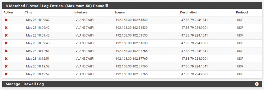
Extra note: It’s advisable to block outgoing traffic from camera into internet. My camera is connecting to some IP with weird ports.

Quick whois showed me this IP belongs to alibaba.com. I did not sniff the traffic, so I’m not sure if the nature of it is spyware. It’s probably their cloud service or some other service.

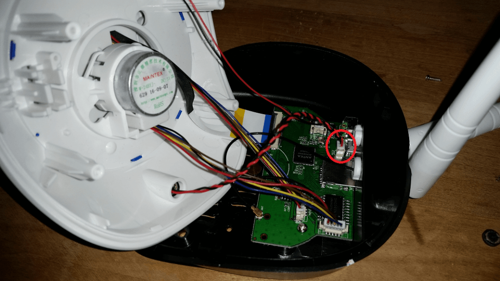
For the extra paranoid, physically disconnect the microphone on the camera:

UPDATE: Apparently they are willing to refund me via 3rd party company (Bluesnap) that handles paysafecard payment processor for them. And if that’s not enough, that I have to utilize 3rd party business to get my money back, guess what, they are unable to refund me directly to my paysafe account, they require my bank account name, IBAN and BIC. They make it almost impossible to get your money back. Avoid PureVPN scammers.

—————————————————————————————————————————————————————————

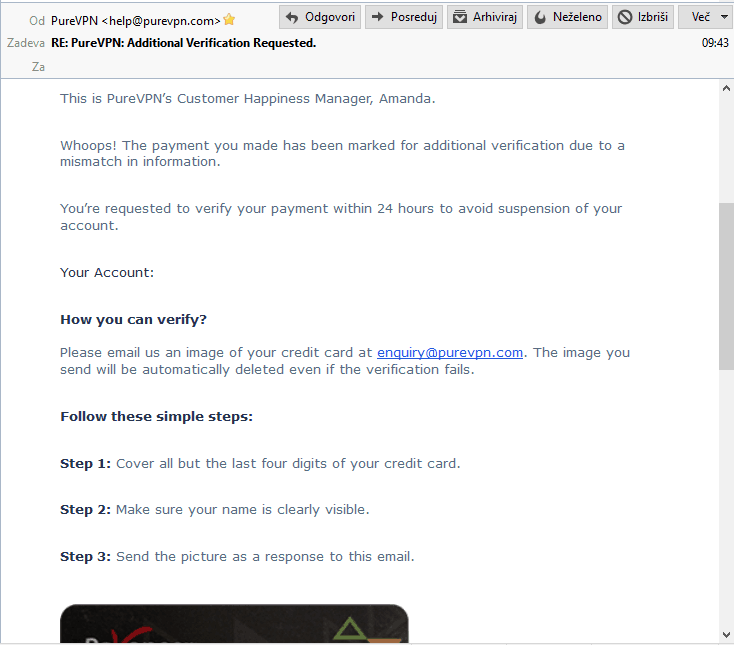
So this is what happened. I was looking for a VPN service that does not require a credit card, because I don’t have one. Then I found PureVPN, they have a lot of payment options including paysafe card. I went to the gas station, purchased paysafe card and funded my account. I bought PureVPN 2 year package for 69$ with paysafe card. To my surprise, VPN stopped working few hours after the purchase was made. I’ve checked my email and received a messsage from them noticing me about my VPN account being disabled due security measures. They wanted me to verify my account by sending them a scan of my credit card. So, WTF, I bought their service with paysafe card because I don’t have a credit card, and they want me to verify the account with the credit card? Why would I even buy their service with paysafe card if I had a f*****g credit card? Where’s the logic behind that? I replied to their message and told them I don’t have a credit card and if they don’t like it they should just refund me. They replied with some bullshit generic text “about caring for the customers, jada jada, bullshit, more bullshit”. On the top of that email, they sent another generic mail noticing me that they will suspend my account if I don’t verify it, with a credit card. Really, did you even read what I’ve wrote the last time about not having a credit card? So, their lack of understanding about my situation and not mentioning it in the replies by just sending me generic non personalized emails tells me that they are scammers and they are stealing money from customers. Also, the service sucks, during a few hours I had a chance to test their service I tried many different servers on a different continents. I have a 220 mbit line but their VPN bandwidth never exceeded 50/60 mbit. So F*** you PureVPN scammers, you can keep my money and shove it up your a**. I will never recommend your fraudulent services to anyone else ever. DO NOT BUY PUREVPN.

TL;DR:

  • Bought PureVPN with paysafe card because I don’t have a credit card
  • They disabled my account and wanted verification by sending them a scan of a credit card that I obviously don’t have
  • They did not want to refund me, they ignored my issue about not having a credit card
  • Service sucks, low bandwidth
  • DO NOT BUY PUREVPN

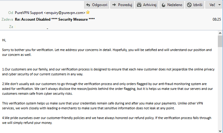
1st security measure email:

My reply:

Their second and third reply:

TL;DR:

Xerox phaser 3020 black ink percentage remaining – SNMP cacti data and graph template at the bottom of this post.


With some tweaks this method should also works for other brand printers.

With the help of this article: https://thwack.solarwinds.com/docs/DOC-171511 I could set up a cacti template for my Xerox 3020 printer. Some printers return ink level value in percents but in my case I got only the raw value.

1. Get SNMP toner max capacity value, OID for that is 1.3.6.1.2.1.43.11.1.1.8.1.1

root@cacti: snmpget -v2c -c public 192.168.0.251 1.3.6.1.2.1.43.11.1.1.8.1.1
SNMPv2-SMI::mib-2.43.11.1.1.8.1.1 = INTEGER: 700

700 is the raw value for 100% toner capacity.

2. Get SNMP toner current levels value, OID for that is 1.3.6.1.2.1.43.11.1.1.9.1.1

root@cacti: snmpget -v2c -c public 192.168.0.251 1.3.6.1.2.1.43.11.1.1.9.1.1
SNMPv2-SMI::mib-2.43.11.1.1.9.1.1 = INTEGER: 686

686 is the current raw value of my toner levels. To calculate toner ink percentage remaining we need to divide current raw value (686) with max raw value (700) and multiply it by 100. 686 / 700 * 100 = 98 (percentage of ink remaining). Since the max raw value is a nice number (700), we can just divide current raw value with 7, 686/7 = 98. We can use this formula for our CDEF definitions in cacti later. Remember, this is only for Xerox 3020, other brand printers can output different raw values and you need to correct this formula accordingly.

Xerox 3020 ink remaining percentage formula: raw_current_ink_level / 7

3. Login to cacti and go to Console -> Presets -> CDEFs

Click plus sign and create new CDEF and name it Xerox toner percentage

Click plus at CDEF Items.

CDEF Item Type: Special Data Source

CDEF Item Value: Current Graph Item Data Source

Click Save

Click plus at CDEF Items.

CDEF Item Type: Custom String

CDEF Item Value: 7 (this is the value cacti will use to divide raw data)

Click Save

Click plus at CDEF Items.

CDEF Item Type: Operator

CDEF Item Value: / (this will tell cacti to use a divide operation with the custom string we defined in a previous step).

Click Save

4. Go to Console -> Templates -> Data Source

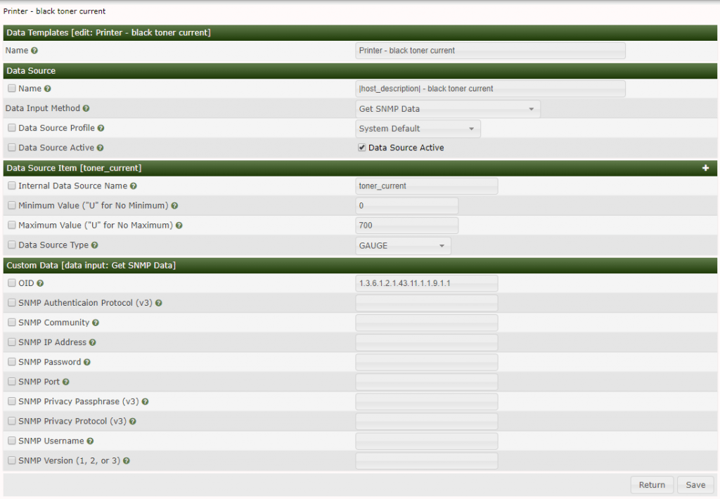
Click plus to create new data source template and name it Printer – black toner current

Name: |host_description| – black toner current

Data Input Method: Get SNMP Data

Data Source Active: tick the right box

Internal Data Source Name: toner_current

Click Create

New Custom Data field will appear.

OID: 1.3.6.1.2.1.43.11.1.1.9.1.1

Click Save

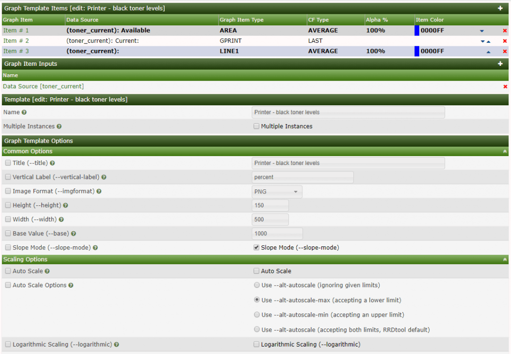
5.1 Go to Console -> Templates -> Graph

Click plus sign

Name: Printer – black toner levels

Title: Printer – black toner levels

Vertical Label: percent

Tick Rigid Boundaries Mode

Upper Limit: 100

Click Create

5.2 Now click plus sign at Graph Template Items

Graph Item Type: AREA

Data Source: Printer – black toner current

Color: select what you like

Consolidation Function: AVERAGE

CDEF Function: Xerox toner percentage

Text Format: Available

Click save

Add another Graph template item

Graph Item Type: GPRINT

Data Source: Printer – black toner current

Consolidation Function: LAST

CDEF Function: Xerox toner percentage

GPRINT Type: Percent(Round down to the nearest decimal)

Text format: Current:

Click Save

Add another Graph template item

Graph Item Type: LINE1

Data Source: Printer – black toner current

Consolidation function: AVERAGE

CDEF function: Xeror toner percentage

Save

Your graph is now ready to device assignment.

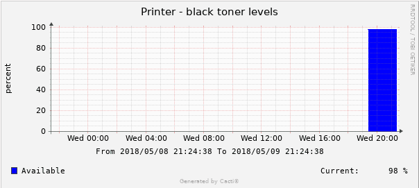
Final result:

Download data and graph templates for xerox phaser 3020:

xerox_3020_cacti_toner_level_template


TL;DR:

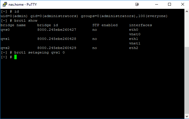
  1. SSH login to QNAP
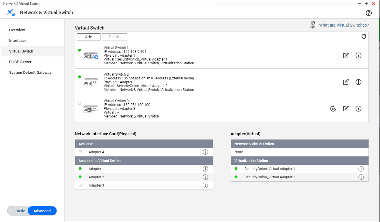
  2. Identify virtual switch you want to put into monitoring mode, in my case qvs1
  3. Set ageing to 0
brctl show
brctl setageing qvs1 0

My example:

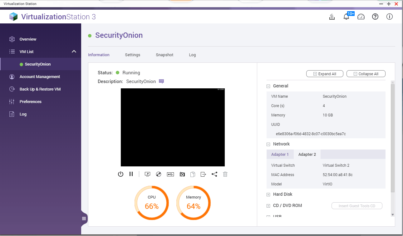
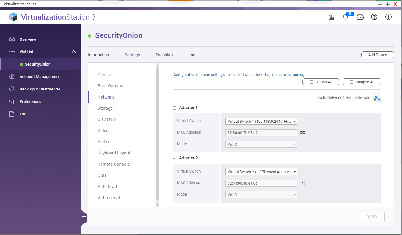
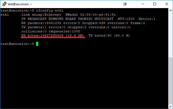
I’ve created a virtual machine  (SecurityOnion) on my QNAP virtualization station to monitor my home network traffic. I have setup a port mirroring on my switch to send all traffic to the QNAP ethernet adapter number 2. (My QNAP has 4 ethernet adapters). Sniffing OS usually needs two ethernet adapters, one for management and one dedicated for monitoring (sniffing). I’ve created a new virtual switch in QNAP with adapter number 2 and set it to external mode (no IP address), then I assigned this virtual switch to monitoring interface in SecurityOnion. I should’ve been able to see all the traffic now, but that wasn’t the case. There were no packets flowing to my monitoring ethernet adapter. After some investigating I found out a reddit user had the same problem. This is the solution:

SSH into your QNAP with your admin username and credentials. Check your virtual switches with a command “brctl show“, this will list all virtual switches you created. Now you need to select the virtual switch you assigned to your sniffing ethernet adapter in my case, that was adapter number 2 and run the following command: “brctl setageing qvs1 0″, where qvs1 is the number of your selected virtual switch (one that will do the sniffing, in my case adapter 2, identified as qvs1). That’s it, you should see all packets on the sniffing interface now. Thanks go to the reddit user I don’t want to name due privacy concerns.

SecuritOnion is now receiving packets on the monitoring interface:

Side note: Sniffing and analyzing traffic is heavy on CPU, HDD and RAM resources. Qnap is not a suitable candidate for that. My Qnap tests showed a CPU bottleneck (quad core celeron N3160) averaging around 70% cpu usage with low network traffic and less than 20 devices on the network.

I wanted to limit upload speed of my torrent clients (utorrent, qbittorent) with port forwarding enabled. This can be done on the client itself but I prefer the method via firewall.

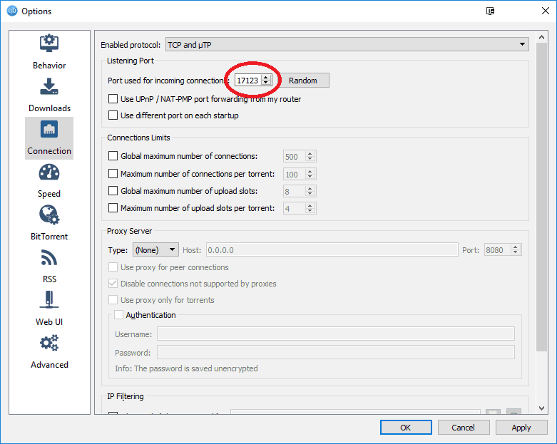
For this example I forwarded port 17123 to my qbittorent client and limited upload speed to 1mbit/s. There are probably other more “proper” methods to achieve this on Pfsense, but this is working for me:

Set up a port in a client:

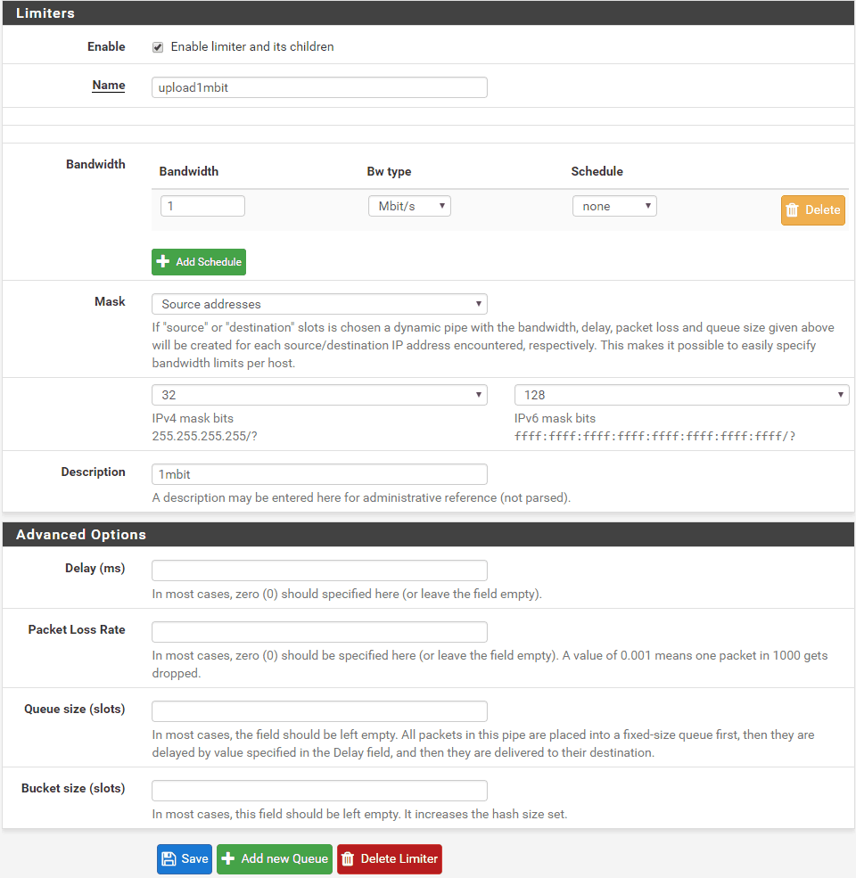
Go to Pfsense, Firewall, traffic shaper, limiters:

Click New limiter

Tick Enable limiter and its children

Name it upload1mbit

Set Bandwidth to 1 Mbit/s

Set Mask to Source addresses and set Description to something you like and save.

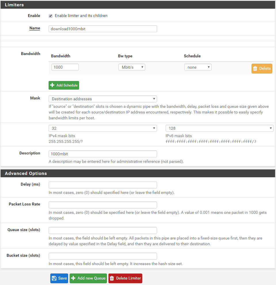
For limiters to work you also need to make a download limiter. Click new limiter and name it download1000mbit

Set bandwidth to 1000 Mbit/s

Set mask to Destination addresses

Set description and click save.

Now go to firewall, NAT and add a new rule:

Interface: WAN

Protocol: Depends on your needs, usually TCP, UDP or both

Destination: WAN address

Destination port range: 17123 to 17123

Redirect target IP: LAN IP of the machine torrent client is running on, example 192.168.0.2

Redirect target port: 17123

Description: Torrents

Click Save


Now go to firewall, rules, WAN and find the associated rule we created in the previous step, click edit.

Scroll down to the bottom and click Display Advanced, scroll down again to find In / Out pipe.

For In select download1000mbit, and for out select upload1mbit, save and apply changes. This is the opposite of what you do when you want to limit LAN IP bandwidth, because this rule is applied to WAN interface not LAN. Click save and the limiter should work. You should always reset the states when applying new settings to filters. You can do that on Diagnostics, states, reset states.

I will add more images later, this is only a quick draft. It should be sufficient to set up a rule though.

1. Update system and optionally disable X Desktop, we don’t need GUI

apt-get update
apt-get upgrade
raspi-config

Select menu: 3, B1, B1

2. Install dependencies

apt-get install subversion libsigc++-2.0-dev g++ make libsigc++-1.2-dev libgsm1-dev screen \
libpopt-dev tcl8.5-dev libgcrypt-dev libspeex-dev libasound2-dev alsa-utils install qt-sdk git groff -y

3. Add a new user

adduser svxlink

4. Download svxlink source

cd /usr/src; wget https://github.com/sm0svx/svxlink/archive/15.11.tar.gz; tar xvf 15.11.tar.gz; cd svxlink-15.11/src; mkdir build; cd build

5. Compile and install svxlink

cmake -DCMAKE_INSTALL_PREFIX=/usr -DSYSCONF_INSTALL_DIR=/etc \
        -DLOCAL_STATE_DIR=/var ..
make
make doc
make install
ldconfig

6. Install sounds

cd /usr/share/svxlink/sounds; wget https://github.com/sm0svx/svxlink-sounds-en_US-heather/releases/download/14.08/svxlink-sounds-en_US-heather-16k-13.12.tar.bz2
tar xvf svxlink-sounds-en_US-heather-16k-13.12.tar.bz2
mv en_US-heather-16k en_US; rm -rf svxlink-sounds-en_US-heather-16k-13.12.tar.bz2

7. Configure sound levels

alsamixer

Press F6 and select usb soundcard.
Press F5 to show all.
Increase gain on CAPTURE, around 80 is fine, experiment otherwise.
Exit alsamixer and save the settings with:

alsactl store

8. Tweak configuration files in /etc/svxlink/svxlink.conf and /etc/svxlink/svxlink.d/ModuleEchoLink.conf

svxlink.conf: I will show you only modified lines

Uncomment LOCATION_INFO=locationInfo to show your Echolink on aprs.fi map.
MODULES=ModuleEcholink
CALLSIGN=Yoursign-L
SHORT_IDENT_INTERVAL=0
LONG_IDENT_INTERVAL=0

Under [Rx1]

AUDIO_DEV=alsa:plughw:1 #Hardware ID of the soundcard, usually 1 on rpi with usb soundcard
SQL_START_DELAY=100 #Prevent TX, RX loop
VOX_THRESH=500 #Increase if your VOX gets falsly opened

Under [Tx1]:

AUDIO_DEV=alsa:plughw:1
PTT_TYPE=SerialPin
PTT_PORT=/dev/ttyUSB0 #Depends what you have for PTT triggering, I do it with RS232 to USB converter

Under [LocationInfo]
#This is mostly self explanatory

APRS_SERVER_LIST=poland.aprs2.net:14580
STATUS_SERVER_LIST=aprs.echolink.org:5199
#Go to maps.google.com, select your location, right click, what's here
#and you'll get coordinates, for example: 45.660325, 14.291537 Go to https://rechneronline.de/winkel/degrees-minutes-seconds.php
#and convert from decimal degrees provided from maps.google.com to degrees, arc minutes, arc seconds.
#Enter converted
#coordinates.

LON_POSITION=14.17.29E
LAT_POSITION=45.39.37N
CALLSIGN=EL-yourcallsign
FREQUENCY=145.275
TX_POWER=5
ANTENNA_GAIN=0
ANTENNA_HEIGHT=5m
ANTENNA_DIR=-1
PATH=WIDE1-1
BEACON_INTERVAL=10
TONE=123
COMMENT=SvxLink by SM0SVX (svxlink.sourceforge.net)

ModuleEcholink.conf:

ALLOW_IP=192.168.0.0/24 #Depends on your home network setup,
#it could be also ALLOW_IP=192.168.1.0/24
SERVERS=europe.echolink.org
CALLSIGN=yoursign-L
PASSWORD=your echolink password
SYSOPNAME=yourname
LOCATION=[Svx] comment about your echolink
LINK_IDLE_TIMEOUT=0
AUTOCON_ECHOLINK_ID=ID of the remote repeater for example AUTOCON_ECHOLINK_ID=609569
AUTOCON_TIME=1200
DESCRIPTION=edit text to fit your needs
reboot

9. Run svxlink

svxlink

Try to transmit, usb soundcards on rpi are tricky. You will probably get a warning:
Rx1: Distorsion detected! Please lower the input volume!
Don’t worry about it.
Exit and run svxlink as daemon

svxlink --daemon

10. Start svxlink at boot
You need to wait some time after boot for Pi to initialize devices.
It will not work when you start svxlink immediately after the boot,
the process will run but there will be no access to PTT. Open
/etc/rc.local and add this two lines at the end of the file, before exit 0

sleep 120
/bin/bash -c '/usr/bin/svxlink --pidfile=/var/run/svxlink.pid --daemon'

This will start svxlink 2 minutes after boot.

#!/bin/bash

# Rtsp to youtube streaming with ffmpeg

VBR="1000k" # Bitrate of the output video, bandwidth 1000k = 1Mbit/s
QUAL="ultrafast" # Encoding speed
YOUTUBE_URL="rtmp://a.rtmp.youtube.com/live2" # RTMP youtube URL
THREADS="0" # Number of cores, insert 0 for ffmpeg to autoselect, more threads = more FPS

CAMUSER="user"
CAMPASS="password"
CAMIP="192.168.0.2"
CAMPORT="88"
VIDEOCHANNEL="videoSub" # videoMain and VideoSub for Foscam cameras

SOURCE="rtsp://${CAMUSER}:${CAMPASS}@${CAMIP}:${CAMPORT}/${VIDEOCHANNEL}" # Camera source
KEY="xxx-xxxx-xxxx-xxxx" # Youtube account key

# To download fonts
# wget -O /usr/local/share/fonts/open-sans.zip "https://www.fontsquirrel.com/fonts/download/open-sans";unzip open-sans.zip
FONT="/usr/local/share/fonts/OpenSans-Regular.ttf"
FONTSIZE="15"

# Text allingment
x="5"
y="60"

# Other
box="1" # enable box
boxcolor="black@0.5" # box background color with transparency factor
textfile="ffmpeg.txt"
reloadtext="1" # Reload textfile after each frame, usefull for overlaying changing data 
# like weather info. To update the textfile while streaming, you need to use mv command or a crash
# is going to happen when you update the textfile.
# Example:
# wget -q https://something.com/ -O - | grep somevalue > ffmpegraw.txt; mv ffmpegraw.txt ffmpeg.txt
boxborderwidth="5"

# Ffmpeg with drawtext, 
    ffmpeg -loglevel panic \
    -f lavfi -i anullsrc \
    -rtsp_transport tcp \
    -i "$SOURCE" \
    -vcodec libx264 -pix_fmt yuv420p -preset $QUAL -g 20 -b:v $VBR \
    -vf "drawtext="fontfile=${FONT}":textfile=${textfile}:x=${x}:y=${y}:reload=${reloadtext}: \
    fontcolor=white:fontsize=${FONTSIZE}:box=${box}:boxborderw=${boxborderwidth}:boxcolor=${boxcolor}" \
    -threads $THREADS -bufsize 512k \
    -f flv "$YOUTUBE_URL/$KEY"

# Copy stream only, don't encode
#ffmpeg \
#    -f lavfi -i anullsrc \
#    -rtsp_transport tcp \
#    -i "$SOURCE" \
#    -vcodec libx264 -pix_fmt yuv420p -preset $QUAL -g 20 -c:v copy -b:v $VBR \
#    -f flv "$YOUTUBE_URL/$KEY"

Overlayed data over webcam stream example:

To run the script in background you need to add nohup otherwise ffmpeg will hang.

nohup bash this_script.sh &

Ffmpeg likes to crash from time to time. Create a script to check for ffmpeg process and restart it if there is no process running.

#!/bin/bash
#
# Description: Checks for existing ffmpeg process and starts one if needed
#
script=/path/to/first_script.sh

if ! pgrep -x "ffmpeg" > /dev/null
then
    /bin/bash $script > /dev/null 2>&1 &
fi

Save script as check_ffmpeg.sh

chmod +x check_ffmpeg.sh

Run the script with crontab every minute.

crontab -e
* * * * * sudo bash /path_to_script/check_ffmpeg.sh

#!/bin/sh

# Get APRS weather data from aprs.fi

wxstation="S55MA-10"

# Basic weather data
temp="$(wget -q https://aprs.fi/weather/a/${wxstation} -O - | grep Temperature | egrep '[-+]?([0-9]*\.[0-9]+|[0-9]+)' -o)"
humidity="$(wget -q https://aprs.fi/weather/a/${wxstation} -O - | grep Humidity | egrep '[-+]?([0-9]*\.[0-9]+|[0-9]+)' -o)"
wind="$(wget -q https://aprs.fi/weather/a/${wxstation} -O - | grep Wind | egrep '[-+]?([0-9]*\.[0-9]+|[0-9]+)' -o | sed -n -e 2p)"
rain="$(wget -q https://aprs.fi/weather/a/${wxstation} -O - | grep Rain | egrep '[-+]?([0-9]*\.[0-9]+|[0-9]+)' -o | sed -n -e 1p)"

# Telemetry
radioactivity="$(wget -q https://aprs.fi/telemetry/a/${wxstation} -O - | grep Radioactivity | egrep '[-+]?([0-9]*\.[0-9]+|[0-9]+)' -o | sed -n -e 5p)"

printf "%s\n" "Temperature: ${temp}°C" "Humidity: ${humidity}%" "Wind: ${wind} m/s" "Rain: ${rain} mm/h" "Radioactivity: ${radioactivity} uSv/h"